Physics · Ch 5 — Electrostatic Potential and Capacitance
The Parallel Plate Capacitor
The Parallel Plate Capacitor
The Parallel Plate Capacitor
A parallel plate capacitor is the simplest and most common type of capacitor. It consists of two large, plane, parallel conducting plates separated by a small distance. The intervening medium is initially taken to be vacuum.
Why the Plates Must Be Large and Close
The separation between the plates is much smaller than the linear dimensions of the plates (i.e., , where is the area of each plate). This condition allows us to treat each plate as an infinite plane sheet of uniform surface charge density, ignoring edge effects.
Surface Charge Density
If one plate carries charge and the other , the surface charge density on each plate is:
Plate 1 has , plate 2 has .
Electric Field in Different Regions
Using the result for an infinite plane sheet (from Section 1.15), the electric field due to a single sheet is directed away from a positive sheet and toward a negative sheet.
- Outer region I (above plate 1): Fields from both plates cancel.
- Outer region II (below plate 2): Fields again cancel.
- Inner region (between the plates): Fields from both plates add, both pointing from the positive to the negative plate.
Substituting :
The electric field is uniform and confined to the region between the plates. Near the edges, field lines bend outward — this is called fringing of the field — but for , these effects are negligible in the central region.
Potential Difference
For a uniform electric field, the potential difference between the plates is simply the field times the separation :
Capacitance
Capacitance is defined as . Using the expression for :
The capacitance depends only on the geometry of the capacitor (area and separation ) and the permittivity of free space .
Numerical Example: Why 1 Farad Is Huge …
Drawn by us to help you understand the concept clearly, and verified to make sure it's accurate. For exams, practice from your textbook's own diagram.
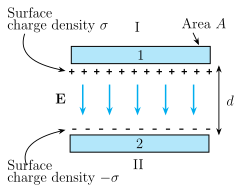
The figure shows two horizontal conducting plates placed parallel to each other, with a small gap between them. The upper plate is labelled '1' and the lower plate '2'. On the underside of plate 1, a row of '+' signs indicates a positive charge, while on the top side of plate 2, a row of '−' signs indicates an equal amount of negative charge. Between the plates, vertical arrows pointing downward are labelled E, showing that the electric field is uniform and directed from the positive plate to the negative plate.
On the left side, curved leaders point to the plates: the upper leader reads 'Surface charge density ' (for plate 1), and the lower leader reads '' (for plate 2). This indicates that the charge per unit area on each plate is uniform in magnitude but opposite in sign. The region 'I' is marked in the upper-left (above plate 1), and region 'II' in the lower-left (below plate 2). On the top-right, a leader points to the upper plate and reads 'Area A', meaning each plate has the same area . On the right side, a vertical double-headed arrow labelled spans the separation between the plates.
The physical idea taught by this figure is that a parallel plate capacitor stores charge by creating a uniform electric field confined almost entirely to the region between the plates. Because the plate separation is much smaller than the linear dimensions of the plates (), edge effects (fringing) can be ignored, and the field is the same as that due to two infinite plane sheets of charge.
The key formulas developed from this figure are:
- The electric field in the inner region (between the plates) is the sum of the fields from each plate: …