Q.(a)
🔒You're viewing a preview — the full solution, concept, methods & PYQ mapping are locked.
🔒 Start your 14-day free trial to unlock the full solution →Part (a)Concept understanding — Motional Emf
Motional Emf
When a conductor moves through a magnetic field, the free charges inside it experience a magnetic force. This force pushes the charges along the conductor, setting up a potential difference across its ends — a motional emf. It is electromagnetic induction viewed from a moving conductor rather than from a changing field.
Origin: the Lorentz force
Consider a straight rod of length l moving with velocity v perpendicular to a uniform field B. Each free charge q feels a force
F=q(v×B)
of magnitude qvB directed along the rod. Charges pile up at the ends until the electric field they create balances the magnetic force. The resulting potential difference — the motional emf — is
ε=Bvl
Consistency with Faraday's law
Let the rod of length l slide along parallel conducting rails, sweeping out a distance x. The enclosed area is A=lx, so the flux is Φ=Blx. Then
ε=−dtdΦ=−Bldtdx=−Blv
The magnitude Bvl matches the Lorentz-force result, showing that the flux rule and the force picture agree.
Worked example
A rod of length 0.4m moves at 5m/s perpendicular to a field of 0.5T:
ε=Bvl=0.5×5×0.4=1V
If the circuit resistance is 2Ω, the induced current is I=ε/R=0.5A.
Force and energy …
Why this formula?
Motional EMF: Why the Formula Holds
Let's build this from first principles — understanding the why before the formula.
The Core Idea
Motional EMF arises when a conductor moves through a magnetic field. The key insight: moving charges in a magnetic field experience a magnetic force, which acts like a battery pushing charges around the conductor.
Step 1: The Force on a Moving Charge
A charge q moving with velocity v in a magnetic field B feels the Lorentz magnetic force:
Fm=q(v×B)
This force is perpendicular to both velocity and magnetic field.
Step 2: What Happens Inside a Moving Conductor
Consider a straight metal rod of length L moving with constant velocity v perpendicular to a uniform magnetic field B (pointing into the page).
- Free electrons in the rod are moving with the rod at velocity v.
- Each electron experiences a magnetic force:
Fm=−e(v×B)
(negative sign because electron charge is −e)
- This force pushes electrons along the rod — say, toward one end.
Step 3: Charge Separation Creates an Electric Field
As electrons accumulate at one end, that end becomes negatively charged, leaving the other end positively charged.
- This charge separation creates an internal electric field E inside the rod, pointing from positive to negative end.
- The electric field exerts an opposing force on the electrons:
Fe=−eE
Step 4: Equilibrium — The "Battery" is Formed
Charge keeps moving until the electric force balances the magnetic force:
Fe+Fm=0
−eE−e(v×B)=0
E=−(v×B)
Magnitude-wise (for perpendicular v and B):
E=vB
Step 5: From Electric Field to EMF
The motional EMF E is the work done per unit charge to move a test charge from one end to the other:
E=∫negativepositiveE⋅dl
For a uniform field along the rod of length L:
E=E⋅L=vBL
The Key Formula
Motional EMF for a straight conductor moving perpendicular to B:
E=BLv
Why This Makes Physical Sense
| Quantity | Role |
|---|---|
| B | Stronger magnetic field → larger force on charges |
| L | Longer conductor → more charge separation possible |
Part (b)Concept understanding — Ampere's Circuital Law
The Intuition: What Ampere's Law Is Really Saying
Imagine you're standing in a field of grass, and you walk in a complete circle. If the grass is perfectly flat and still, your path feels the same all the way around. But if there's a strong wind blowing through the center of your circle, you'll feel it push you differently at different points along your walk.
Electric currents create magnetic fields. Ampere's Circuital Law is a way of measuring how much magnetic field is swirling around a current — like measuring how strong the "whirlpool" of field lines is around a wire.
The key idea: if you take a closed loop (any shape you like) and add up the magnetic field along every tiny piece of that loop, the total you get is directly proportional to the amount of current that passes through the loop. No current through the loop? The total is zero.
This is the magnetic analogue of Gauss's Law for electricity. Gauss's Law relates the flux of electric field through a closed surface to the charge inside. Ampere's Law relates the circulation of magnetic field around a closed loop to the current inside.
The Precise Statement
Ampere's Circuital Law states:
∮B⋅dl=μ0Ienc
Let's break down every symbol:
- ∮ — The circle on the integral sign means you're integrating around a closed loop. You start at some point, trace a complete path, and return to where you began.
- B — The magnetic field at each point on your loop.
- dl — An infinitesimally small piece of your loop, treated as a vector pointing along the direction you're walking.
- B⋅dl — The dot product. This picks up only the part of the magnetic field that points along your path. If the field is perpendicular to your path at some point, that piece contributes nothing.
- μ0 — The permeability of free space, a fundamental constant (4π×10−7T⋅m/A). It tells you how "strongly" a current creates a magnetic field in empty space.
- Ienc — The net current passing through the area bounded by your loop. "Net" means you add currents going one way and subtract currents going the opposite way.
The current must pass through the loop's opening — not just anywhere near it. A current that runs outside the loop contributes zero to the right-hand side, even if it produces a magnetic field at points on the loop.
Why the Dot Product Matters
The dot product B⋅dl=Bdlcosθ where θ is the angle between the field and your path. This is crucial: if you walk along a path where the magnetic field is always perpendicular to your direction, you get zero contribution at every step — even if the field is huge.
This is why Ampere's Law is most useful for symmetric situations. You choose your loop so that:
- The magnetic field is constant in magnitude along the loop.
- The field is always parallel (or antiparallel) to your path, so cosθ=±1.
Then the integral becomes simple multiplication: B×(circumference of loop)=μ0Ienc.
The Classic Example: A Straight Wire
Consider an infinitely long, straight wire carrying current I. The magnetic field circles around the wire in concentric circles. Choose your Amperian loop to be a circle of radius r centered on the wire.
By symmetry, B is the same at every point on the circle and points tangent to it — exactly along dl. So:
∮B⋅dl=B×(2πr)=μ0I
Therefore:
B=2πrμ0I
This is the familiar formula for the field around a long straight wire. Notice: the field falls off as 1/r, not 1/r2 like the electric field from a point charge. Magnetic fields from currents have a different geometry.
| Configuration | Amperian Loop | Result |
|:---|:---|:---|
| Straight wire | Circle centered on wire | B=2πrμ0I | …
Part (a)
- Lenz's law. The induced current in a closed circuit flows in a direction that opposes the change in magnetic flux producing it. This follows from conservation of energy: if the induced current aided the change, it would reinforce the cause and the system would generate electrical energy without external work — a perpetual motion machine. So the current must oppose the change, and the work done against this opposition appears as the electrical energy.
- EMF of a rotating rod. The rod (L=2m) rotates about its centre, so from centre to end the length is ℓ=L/2=1m. Angular frequency ω=2πf=2π(60)=120πrad/s. For a rod rotating in a perpendicular field B, …
Part (a): Lenz's law (opposing induced current) is a statement of energy conservation; the emf between the centre and end of the rotating rod is 21Bωℓ2=120π≈377V. Part (b): Ampere's law relates ∮B⋅dl to the enclosed current; the net field midway between the two wires is 1.0×10⁻⁵T, along the 10A wire's field.
Part (a)
(i) Lenz's law and energy conservation
Lenz's law: the direction of the induced emf (and current) is always such that it opposes the change in magnetic flux that produces it.
Justification. If the induced current instead aided the flux change, the resulting force would push the system further in the same direction, so it would speed up on its own and deliver electrical energy with no work input — energy created from nothing, violating conservation of energy. Hence the induced current must oppose the change; the external agent does work against the opposing force, and that work is what appears as electrical energy.
(ii) EMF of the rotating rod
The rod is rotated about its centre, so the segment from centre to one end has length
ℓ=22m=1m.
Angular frequency:
ω=2πf=2π(60)=120πrad/s.
Each element at distance x moves with speed ωx; integrating the motional emf ∫0ℓBωxdx gives …
Showing the 12 most recent of 13 on this concept.
- CBSE 2026Set 55/1/11 markMCQQ.A long straight wire of circular cross-section (radius a) carries a steady current I. The current is uniformly distributed across this cross-section. The magnitude of the magnetic field produced at a point at a distance (2a) from the axis of the wire will be (A) Zero (B) 2πaμ0I (C) 4πaμ0I (D) 6πaμ0I
›Reveal solutionSolution
For a current uniformly distributed across a wire's cross-section, the magnetic field inside the wire grows linearly with distance from the axis. At r=a/2, the field is half its surface value, giving 4πaμ0I, which corresponds to option (C).
The key insight here is that the magnetic field inside a current-carrying conductor depends only on the current enclosed by the Amperian loop, not the total current. For a uniform current density, the enclosed current scales with the area of the loop, so the field inside increases linearly with r.
Let's work through this systematically.
-
Set up the problem. We have a long straight wire of radius a carrying a steady current I, uniformly distributed over its cross-section. We need the magnetic field at a distance r=a/2 from the axis — that's a point inside the wire.
-
Recall Ampere's Law. For a long straight wire with cylindrical symmetry, Ampere's Law states:
∮B⋅dl=μ0Ienc
where Ienc is the current passing through the surface bounded by the Amperian loop. By symmetry, B is tangential and constant in magnitude along a circular path of radius r, so:
B⋅(2πr)=μ0Ienc
- Find the current enclosed at r=a/2. Since the current is uniform, the current density is:
J=πa2I
The area enclosed by our Amperian loop of radius r is πr2, so:
Ienc=J⋅πr2=πa2I⋅πr2=Ia2r2
- Apply Ampere's Law. Substitute Ienc into the equation:
B⋅(2πr)=μ0(Ia2r2)
Solve for B:
B=2πa2μ0Ir
Binside=2πa2μ0Ir …
-
- CBSE 2026Set ANNUAL1 markMCQQ.Which of the following formula represents Ampere's circuital law?(i) ∮B⋅dl=μ0I(ii) φE=ϵ01(q)(iii) dB=4πμ0r3Idl×r(iv) I=RV
›Reveal solutionSolution
Ampere's circuital law relates the line integral of B around a closed loop to the enclosed current.
Ampere's circuital law states that the line integral of magnetic field B around any closed path equals μ0 t …
- CBSE 2026Set ANNUAL1 markMCQQ.A bicycle wheel with 10 spokes is rotating at a rate of 2 Cycle Per Second perpendicular to the horizontal component of the earth's magnetic field. This produces an induced emf 'E' between the axle and rim of the wheel. If the number of spokes is doubled, then the value of induced emf will be(a) 4E(b) 2E(c) E(d) E/2
›Reveal solutionSolution
Each spoke is an independent conducting rod rotating about the same axle in the same field, so each develops the SAME emf; connecting more of them in parallel between axle and rim does not add up their emfs, so E stays unchanged.
For a single conducting rod of length R rotating with angular speed omega in a field B (perpendicular to the plane of rotation), the motional emf between the centre and the rim is E = (1/2) B omega R^2. Every spoke, being identical in length and rotating at the same rate in the same field, develops this same emf E between the axle and the rim. All spokes are connected between the same two po …
- CBSE 2026Set ANNUAL1 markMCQQ.A conducting rod of length l, rotates about one of its ends in a uniform magnetic field B, with a constant angular velocity ω. If the plane of rotation is perpendicular to B, the e.m.f. induced between the ends of rod is ______.(a) (1/2)Bωl²(b) Bωl²(c) 2Bωl²(d) Bωl
›Reveal solutionSolution
A rod rotating about one end sweeps out a circle; summing the motional emf Bvdr over its length gives ε=21Bωl2.
Consider a small element of the rod at distance r from the pivoted end, of length dr. Its linear speed is v=ωr (perpendicular to the rod, in the plane of rotation, hence also perpendicular to B). The motional emf induced across this element is:
dε=Bvdr=Bωrdr
…
- CBSE 2026Set ANNUAL1 markQ.Match the Column A with Column B and write the correct pair. Column A: Motional emf. Column B:(i) μ₀nI,(ii) Volt × second,(iii) μ₀nI/2,(iv) Volt × meter,(v) Volt × meter⁻¹,(vi) Volt.
›Reveal solutionSolution
Motional emf ε = Bvl is a voltage; its unit is volt, option (vi).
When a conductor of length l moves with velocity v perpendicular to a magnetic field B, an emf is induced across it: ε = Bvl. This is an electromotive force, so its …
- CBSE 2025Set ANNUAL1 markMCQQ.A conductor of length 'l' is moving with velocity 'v' parallel to a magnetic field of intensity 'B'. The induced e.m.f. in the conductor will be(a) lvB(b) (1/2) lvB(c) zero(d) (1/2) l^2 vB
›Reveal solutionSolution
Motional EMF in a moving conductor comes from the magnetic force on its free charges, which depends on v x B; if v is parallel to B this cross product vanishes.
The motional EMF induced in a straight conductor of length l moving with velocity v in field B is:
emf = (v x B) . l = B v l sin(phi)
where phi is the angle between v and B. Here the conductor moves parallel to the magnetic field, so phi = 0 degrees, and sin(0) = 0.
emf = B v l sin(0) = 0
…
- CBSE 2024Set A11 markMCQQ.A current I flows along the length of an infinitely long, straight thin walled pipe, then the magnetic field(a) at all points inside the pipe is same but not zero(b) at any point inside the pipe is zero(c) is zero only on the axis of the pipe(d) is different at different points inside the pipe
›Reveal solutionSolution
(b) at any point inside the pipe is zero …
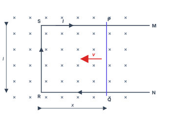
- CBSE 2023Set 55/1/11 markMCQQ.Figure shows a rectangular conductor PSRQ in which the movable arm PQ has resistance r and the resistance of PSRQ is negligible. When PQ is moved with a velocity v, the magnitude of the emf induced does not depend on :(a) magnetic field (B)(b) velocity (v)(c) resistance (r)(d) length of PQ
›Reveal solutionSolution
The induced emf in a moving conductor in a uniform magnetic field is purely a motional emf given by E=Blv, which depends only on the magnetic field B, the length l of the moving arm, and its velocity v. The resistance r of the arm does not appear in this expression — it only determines the current that flows. Hence the correct answer is (c).
The key idea here is the distinction between induced emf and induced current. Many students mix them up, especially when a problem mentions resistance. Let's clear that up first.
When a conductor moves in a magnetic field, the free electrons inside it experience a magnetic Lorentz force q(v×B). This force pushes charges along the conductor, creating a potential difference — that potential difference is the motional emf. It is a direct consequence of the motion and the field, nothing else.
The resistance of the conductor only comes into the picture when you ask: "How much current flows as a result of this emf?" That's Ohm's law: I=E/R. But the emf itself is independent of the resistance.
Now let's walk through the problem step by step.
-
Identify the source of emf. The arm PQ is the only part of the loop that is moving. The rest of the loop (PSRQ) is stationary and has negligible resistance. So the entire induced emf in the loop is generated across PQ.
-
Write the expression for motional emf. For a straight conductor of length l moving with velocity v perpendicular to a uniform magnetic field B, the motional emf is:
E=Blv
This is derived from the work done per unit charge by the magnetic force: Fm=qvB, so the electric field set up inside the conductor is E=vB, and over length l, the potential difference is El=Blv.
- Check each option against this formula.
- (a) magnetic field B — appears in E=Blv. So emf does depend on it.
- (b) velocity v — appears directly. So emf does depend on it.
- (d) length of PQ — that's l in the formula. So emf does depend on it.
- (c) resistance r — does not appear in E=Blv. So emf does not depend on it. …
-
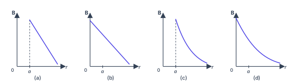
- CBSE 2023Set 55/3/11 markMCQQ.Which of the following graphs correctly represents the variation of the magnitude of the magnetic field outside a straight infinite current-carrying wire as a function of the distance r from the centre of the wire ?(a)(b)(c)(d)
›Reveal solutionSolution
Figure — CBSE 2023 55/3/1 Q4 Outside an infinite current-carrying wire, Ampère's law gives B=2πrμ0I, a 1/r hyperbola starting at the surface r=a. The correct graph is (c).
The magnetic field around a long straight wire is one of the cleanest applications of Ampère's circuital law. The key insight is that the field depends only on the current enclosed by your Amperian loop, and symmetry forces the field to be tangent to circles centered on the wire.
For a wire of radius a carrying current I, the field behaves differently inside and outside. We care about the outside region, r≥a.
Why the field varies as 1/r
- Ampère's law on a circular loop of radius r>a Draw a circle of radius r centered on the wire. By symmetry, B is constant in magnitude along this circle and tangent to it. Ampère's law states:
∮B⋅dl=μ0Ienc.
The left side is simply B⋅2πr (the field magnitude times the circumference). The enclosed current is the total wire current I. So:
B⋅2πr=μ0I.
- Solve for B Rearranging:
B=2πrμ0I.
This is an inverse relationship: as you move farther from the wire, the field drops off as 1/r. Mathematically, this is a rectangular hyperbola.
- The domain: r≥a The formula B=2πrμ0I applies outside the wire, meaning r≥a. At the surface r=a, the field reaches its maximum value for the outside region:
Bmax=2πaμ0I.
For r>a, the field decreases smoothly as 1/r.
B(r)=2πrμ0I,r≥a.
Reading the graphs
Now compare the four options:
Graph Shape Surface marker at r=a Verdict (a) Linear fall-off Yes Wrong shape (not 1/r) (b) Linear fall-off No Wrong shape, no reference to a (c) Hyperbolic 1/r Yes Correct - CBSE 2023Set ANNUAL1 markMCQQ.Direction of current induced in a wire moving in a magnetic field is found using(1) Fleming's left hand rule(2) Fleming's right hand rule(3) Ampere's rule(4) none of these
›Reveal solutionSolution
Fleming's right-hand rule gives the direction of INDUCED current (a motional-EMF/generator situation); the left-hand rule instead gives the direction of FORCE on a current-carrying conductor (a motor situation).
…
- CBSE 2022Set ANNUAL1 markQ.When a metal rod of length l is placed normal to a uniform magnetic field B and moved with a velocity v perpendicular to the field, the induced emf (called motional emf) across its end is ............ .
›Reveal solutionSolution
The induced (motional) emf across the ends of the rod is ε=Bvl.
When a conducting rod of length l moves with velocity v perpendicular to a uniform magnetic field B (with B, v and the rod's length mutually perpendicular), each free charge experiences a magnetic force qvB. This separates charge until an electric field balances it, producin …
- CBSE 2020Set 55/2/11 markQ.A conducting rod of length l is kept parallel to a uniform magnetic field B. It is moved along the magnetic field with a velocity v. What is the value of emf induced in the conductor ?
›Reveal solutionSolution
When a rod moves parallel to a magnetic field, the velocity and field are aligned, so the magnetic flux through any loop remains constant and no emf is induced. The answer is zero.
Why motional emf depends on perpendicular motion
Motional emf arises when a conductor cuts through magnetic field lines. The physical picture: as the rod moves, the magnetic force F=q(v×B) pushes charge carriers along the rod, creating a potential difference. This force—and hence the emf—depends critically on the component of velocity perpendicular to the magnetic field.
The motional emf in a straight rod is given by
E=∫(v×B)⋅dl
For a uniform field and velocity, this simplifies to
E=(v×B)⋅l
where l is the length vector along the rod. The cross product v×B measures how much the velocity is perpendicular to the field. When v and B are parallel (or antiparallel), this cross product vanishes.
Step-by-step analysis
-
Identify the geometry
The rod of length l is parallel to B, and it moves with velocity v along the direction of B. So v∥B.
-
Compute the cross product
Since v and B point in the same (or exactly opposite) direction, the angle θ between them is either 0° or 180°. The magnitude of the cross product is
∣v×B∣=vBsinθ=vB⋅0=0
- Evaluate the motional emf Substituting into the emf formula, …
-
🎓Unlock everything free for 14 days
- ✓Full step-by-step solutions
- ✓Concept-first explanations
- ✓Methods, shortcuts & mistakes
- ✓PYQ mapping + timed mock tests
Full access for 14 days. No credit card required.