Question
Q.(a)
(i) You are given three circuit elements X, Y and Z. They are connected one by one across a given ac source. It is found that V and I are in phase for element X; V leads I by for element Y; while I leads V by for element Z. Identify the elements X, Y and Z.
(ii) Establish the expression for the impedance of the circuit when elements X, Y and Z are connected in series to an ac source. Show the variation of current in the circuit with the frequency of the applied ac source.
(iii) In a series LCR circuit, obtain the conditions under which
(1) the impedance is minimum, and
(2) wattless current flows in the circuit.
(OR)
(b)
(i) Describe the construction and working of a transformer and hence obtain the relation for in terms of the number of turns of the primary and secondary.
(ii) Discuss four main causes of energy loss in a real transformer.
CBSECBSE Class XII Board 2024Subjective· 5mImportance★★★★★
You're viewing a preview — the full solution, concept, methods & PYQ mapping are locked.
Start your 14-day free trial to unlock the full solution →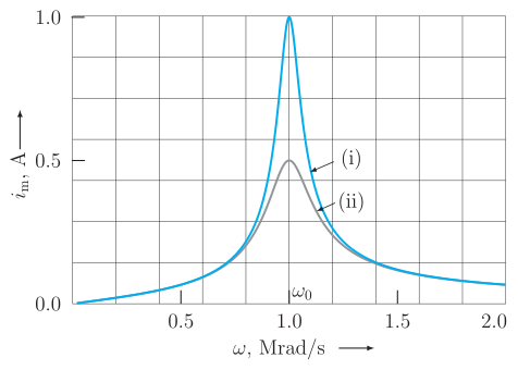
Part (a): X = R, Y = L, Z = C; series impedance , current peaks at resonance (minimum ); wattless current needs . Part (b): A transformer gives ; its four main losses are copper, eddy-current, hysteresis and flux-leakage.
Part (a) — Series LCR circuit
(i) Identifying the elements
- X: V and I are in phase → a pure resistor (R).
- Y: voltage leads current → an inductor (L) (for a pure inductor V leads I by ).
- Z: current leads voltage → a capacitor (C) (for a pure capacitor I leads V by ).
(ii) Impedance in series and frequency response
The three in series carry the same current; their voltage phasors are (in phase), (leading by ) and (lagging by ). Since and are opposite, the reactances subtract. With and ,
Variation with frequency:
- Low : is huge → large → small.
- High : is huge → large → small.
- At the resonant frequency , so (minimum) and (maximum).
The – graph is a resonance curve peaking at .
(iii) Special conditions
(1) Minimum impedance. is least when , i.e.
giving (series resonance). …
Unlock everything free for 14 days
- Full step-by-step solutions
- Concept-first explanations
- Methods, shortcuts & mistakes
- PYQ mapping + timed mock tests
Full access for 14 days. No credit card required.