Q.(a) Explain the characteristic of a p-n junction diode that makes it suitable for its use as a rectifier.
You're viewing a preview — the full solution, concept, methods & PYQ mapping are locked.
Start your 14-day free trial to unlock the full solution →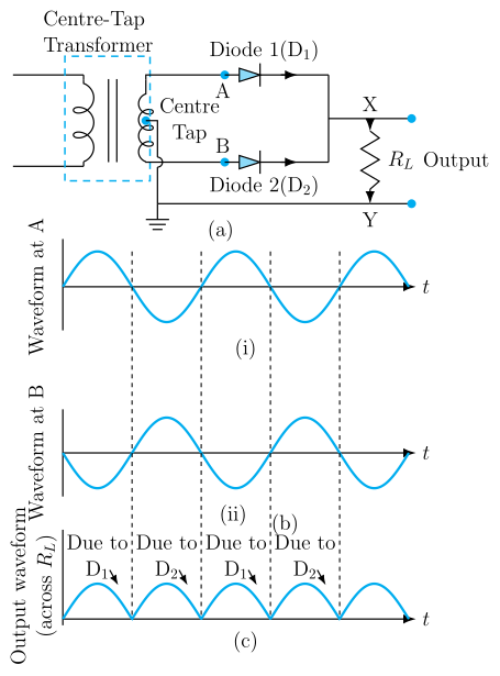
A p-n junction diode conducts current only in one direction (forward bias) and blocks it in the reverse direction — this unidirectional conduction is the key property that makes it suitable for rectification. In a full-wave rectifier, two diodes and a centre-tapped transformer convert both halves of the AC input into a pulsating DC output.
(a) The Characteristic That Makes a p-n Junction Diode a Rectifier
The essential property is rectification — the ability to convert alternating current (AC) into direct current (DC). A p-n junction diode does this because of its asymmetric current-voltage (I-V) characteristic.
-
Forward bias: When the p-side is connected to the positive terminal of a battery and the n-side to the negative, the depletion region narrows. Once the applied voltage exceeds the threshold voltage (about 0.7 V for silicon), a large current flows easily. The diode behaves like a closed switch.
-
Reverse bias: When the polarity is reversed, the depletion region widens. Only a tiny leakage current (microamperes) flows — effectively zero for practical purposes. The diode behaves like an open switch.
For (forward), current grows exponentially. For (reverse), , a negligible constant.
This one-way street for current is what makes the diode a natural rectifier. In an AC signal, the diode allows only the positive half-cycles to pass (or only the negative half-cycles, depending on orientation), blocking the opposite polarity. That's the entire basis of rectification.
A common mistake is to think the diode "converts" AC to DC by changing the waveform's shape. It doesn't — it simply blocks one half of the wave. The output is still pulsating, not a steady DC. Smoothing requires additional components like capacitors.
(b) Full-Wave Rectifier — Circuit and Working
A full-wave rectifier uses two diodes and a centre-tapped transformer to utilise both halves of the AC input cycle. This gives a higher average output voltage and less ripple than a half-wave rectifier.
Circuit Arrangement
- The AC input is applied to the primary coil of a transformer whose secondary winding has a centre tap (midpoint), taken as the common (ground) terminal.
- The two ends of the secondary winding are connected to the p-sides (anodes) of diodes and respectively.
- The n-sides (cathodes) of the two diodes are joined at a common point, and the load resistor is connected between this common cathode point and the centre tap.
Step-by-Step Working
-
During the positive half-cycle of the AC input:
- The upper end of the secondary is positive with respect to the centre tap.
- Diode is forward-biased and conducts.
- Diode is reverse-biased (its anode is at the lower end, which is negative) and does not conduct.
- Current flows: upper end → → load → centre tap → back to the upper end through the transformer winding.
- The output voltage across is positive.
-
During the negative half-cycle of the AC input:
- The lower end of the secondary becomes positive with respect to the centre tap.
- Diode is now forward-biased and conducts.
- Diode is reverse-biased and does not conduct.
- Current flows: lower end → → load → centre tap → back to the lower end.
- The output voltage across is again positive (same direction through the load). …
Unlock everything free for 14 days
- Full step-by-step solutions
- Concept-first explanations
- Methods, shortcuts & mistakes
- PYQ mapping + timed mock tests
Full access for 14 days. No credit card required.