Electronics · Ch 10 — Digital Electronics
Arithmetic logic circuits
Arithmetic logic circuits
Arithmetic logic circuits are logic circuits that carry out arithmetic operations — addition, subtraction and so on — inside a digital computer. In practice only addition and subtraction hardware is needed: multiplication is repeated addition, division is repeated subtraction, and subtraction itself is performed by addition using 1's- and 2's-complement arithmetic. This section covers the three basic building blocks: the half adder, the half subtractor and the full adder. Each is a combinational circuit built only from gates, and each is described by a block diagram, a logic diagram, a truth table and a timing diagram.
Half adder
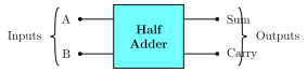
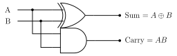
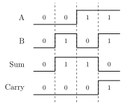
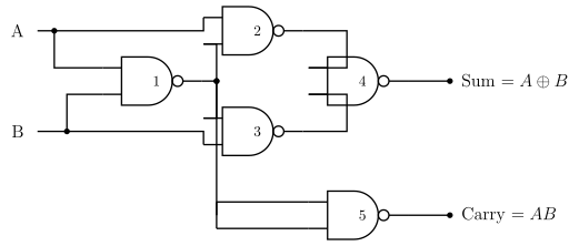
A half adder adds two single bits A and B and produces two outputs — a sum and a carry. The elementary additions are 0+0 = 0, 0+1 = 1, 1+0 = 1 and 1+1 = 10 (binary), where the leading 1 is the carry. From the truth table the sum is an XOR of A and B and the carry is their AND (the Boolean expressions are given in the Half adder outputs card). Its block diagram is figure 10.3.1, its logic diagram (one XOR and one AND) is figure 10.3.2, and its timing diagram is figure 10.3.3. The half adder can also be built entirely from universal NAND gates (figure 10.3.5). Its limitation is that it has no input for a carry coming from a previous stage, so a half adder alone cannot be used for multi-digit addition.
In the printed truth table of the half adder, the fourth input row is misprinted as A = 1, B = 0. It should read A = 1, B = 1, which correctly gives Sum = 0 and Carry = 1. The corrected truth table is shown here.
Half subtractor
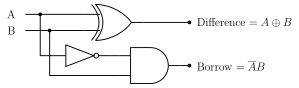
A half subtractor subtracts one bit (the subtrahend B) from another (the minuend A) and produces a difference and a borrow. The elementary operations are 0−0 = 0, 0−1 = 1 with a borrow of 1, 1−0 = 1 and 1−1 = 0. From the truth table the difference is the XOR of A and B and the borrow is HIGH only when A is 0 and B is 1 (the Boolean expressions are given in the Half subtractor outputs card). It is realized with one XOR, one AND and one NOT gate (logic diagram figure 10.3.4), and can also be built using the minimum number of NAND gates.
Full adder …
A logic circuit that performs arithmetic operations (addition, subtraction, etc.) in a digital computer. Multiplication is done as repeated addition, division as repeated subtraction, and subtraction as addition using 1's/2's-complement arithmetic — so adder an …
A combinational circuit that adds two single bits A and B, giving a sum and a carry: Sum = A ⊕ B, Carry = AB. Its limitation is that it has no input for a carry from a previous stage, so it cannot be …
Drawn by us to help you understand the concept clearly, and verified to make sure it's accurate. For exams, practice from your textbook's own diagram.
Figure 10.3.1: a block labelled Half Adder with the two inputs A and B entering on the left and the two outputs Sum and Carry leaving on the right. What to notice: the two outputs are separate — Sum = A ⊕ B is the bit written down and Carry = AB is passed to the next column …
Drawn by us to help you understand the concept clearly, and verified to make sure it's accurate. For exams, practice from your textbook's own diagram.
Figure 10.3.2: inputs A and B feed an XOR gate whose output is Sum = A ⊕ B, and also feed an AND gate whose output is Carry = AB. What to notice: the same two inputs drive both gates in parallel — the XOR produces the sum bit while the AND produces the carry bit; there is no ca …
and . The sum bit is the XOR of A and B (HIGH when they differ) and the carry bit is their AND (HIGH only when both are 1). These two relations follow directly f …
| A | B | Sum = A ⊕ B | Carry = AB |
|---|---|---|---|
| 0 | 0 | 0 | 0 |
| 0 | 1 | 1 | 0 |
| 1 | 0 | 1 | 0 |
| 1 | 1 | 0 | 1 |
Drawn by us to help you understand the concept clearly, and verified to make sure it's accurate. For exams, practice from your textbook's own diagram.
Figure 10.3.3: waveforms A = 0,0,1,1; B = 0,1,0,1; Sum = 0,1,1,0; Carry = 0,0,0,1. Reading the pattern: Sum follows A ⊕ B, HIGH where A and B differ (columns 2 and 3); Carry follows AB, HIGH only in the last column where both A and B are 1 — th …
Drawn by us to help you understand the concept clearly, and verified to make sure it's accurate. For exams, practice from your textbook's own diagram.
Figure 10.3.5: five NAND gates. Gate 1 forms ; gates 2 and 3 form and ; gate 4 gives Sum = A ⊕ B; gate 5 acts as an inverter giving Carry = AB. What to notice: the whole half adder is built from universal NAND gates alone, producing the sa …
A combinational circuit that subtracts one bit B from another bit A, giving a difference and a borrow: Difference = A ⊕ B, Borrow = ĀB (A-complement AND B). Built from one …
Drawn by us to help you understand the concept clearly, and verified to make sure it's accurate. For exams, practice from your textbook's own diagram.
Figure 10.3.4: inputs A and B feed an XOR gate giving Difference = A ⊕ B; A is inverted and ANDed with B to give Borrow = . What to notice: the XOR gives the difference (HIGH when A and B differ), while inverting A before ANDing with B gives the borrow $\overl …
and . The difference bit is the XOR of A and B (HIGH when they differ), matching the half adder's sum; the borrow is HIGH only when …
| A | B | Difference = A ⊕ B | Borrow = ĀB |
|---|---|---|---|
| 0 | 0 | 0 | 0 |
| 0 | 1 | 1 | 1 |
Drawn by us to help you understand the concept clearly, and verified to make sure it's accurate. For exams, practice from your textbook's own diagram.
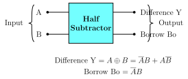
Block diagram (p389): a block labelled Half Subtractor with inputs A and B on the left and outputs Difference Y and Borrow Bo on the right; relations Difference Y = A ⊕ B = $\overline{A}B + A\overline{ …
Drawn by us to help you understand the concept clearly, and verified to make sure it's accurate. For exams, practice from your textbook's own diagram.
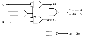
Half-subtractor NAND circuit (p389): a network of five NAND gates producing Difference = A ⊕ B and Borrow = , with intermediate nodes , an …
A combinational circuit that adds three input bits A, B and a carry-in Cin, giving a sum and a carry-out: S = A ⊕ B ⊕ Cin, Co = AB + BCin + CinA. Chaining full adders allows …
Drawn by us to help you understand the concept clearly, and verified to make sure it's accurate. For exams, practice from your textbook's own diagram.
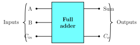
Figure 10.3.6: a block labelled Full adder with three inputs A, B and Cin on the left and two outputs Sum and Co on the right. What to notice: unlike the half adder this block has a third input Cin for the carry from the previous stage, so full adders can be chained to add …
and . The sum S is the XOR of all three inputs (HIGH when an odd number of them are 1), and the carry-out Co is HIGH whenever any two of A, B and Cin are 1 — the …
| A | B | Cin | Sum S | Carry Co |
|---|---|---|---|---|
| 0 | 0 | 0 | 0 | 0 |
| 0 | 0 | 1 | 1 | 0 |
| 0 | 1 | 0 | 1 | 0 |
| 0 | 1 | 1 | 0 | 1 |
| 1 | 0 | 0 | 1 | 0 |
| 1 | 0 | 1 | 0 | 1 |
Drawn by us to help you understand the concept clearly, and verified to make sure it's accurate. For exams, practice from your textbook's own diagram.
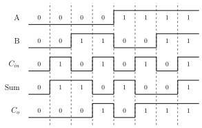
Figure 10.3.7: waveforms A = 0,0,0,0,1,1,1,1; B = 0,0,1,1,0,0,1,1; Cin = 0,1,0,1,0,1,0,1; Sum = 0,1,1,0,1,0,0,1; Co = 0,0,0,1,0,1,1,1. Reading the pattern: over all eight input combinations Sum is HIGH when an odd number of A, B, Cin are 1, and Co is HIGH when two or more are …
Drawn by us to help you understand the concept clearly, and verified to make sure it's accurate. For exams, practice from your textbook's own diagram.
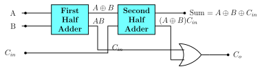
Figure 10.3.8: A and B enter a first half adder giving A ⊕ B and AB; A ⊕ B and Cin enter a second half adder giving Sum = A ⊕ B ⊕ Cin and (A ⊕ B)Cin; the AB and (A ⊕ B)Cin outputs feed an …
Drawn by us to help you understand the concept clearly, and verified to make sure it's accurate. For exams, practice from your textbook's own diagram.
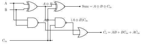
Figure 10.3.9: XOR gate 1 gives A ⊕ B, XOR gate 2 gives Sum = A ⊕ B ⊕ Cin; AND gate 1 gives AB, AND gate 2 gives (A ⊕ B)Cin; an OR gate combines them to give Co = AB + BCin + ACin. What to notice: the two XOR gates build the sum while the two AND gates and the OR collec …
Drawn by us to help you understand the concept clearly, and verified to make sure it's accurate. For exams, practice from your textbook's own diagram.
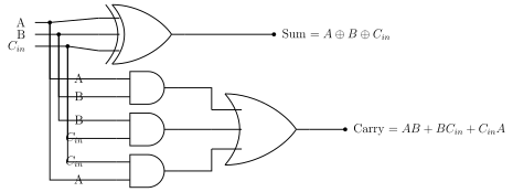
Figure 10.3.10: a single three-input XOR gate gives Sum = A ⊕ B ⊕ Cin; three 2-input AND gates (A,B), (B,Cin), (Cin,A) feed a 3-input OR gate giving Carry = AB + BCin + CinA. What to notice: one three-input XOR forms the sum directly, while three AND gates and an OR form the majority carry — t …