Electronics · Ch 10 — Digital Electronics
Counters
Counters
A counter is a logic circuit that counts pulses. It is a set of flip-flops whose combined state advances through a fixed sequence as pulses arrive at its input. Counters divide broadly into two families:
- Asynchronous (serial / ripple) counters, in which the flip-flops are not clocked together — each stage is triggered by the previous one, so the individual propagation delays add up. They use simple circuitry but are slower and more prone to decoding problems, where states may be momentarily skipped.
- Synchronous (parallel) counters, in which every flip-flop is clocked at the same instant, so the delays do not accumulate. They need more complex circuitry but are faster and count more accurately.
The full comparison is given in the table below.
Four-bit synchronous up-counter
A four-bit synchronous up-counter built from JK flip-flops counts upward in binary 0000, 0001, 0010, …, 1111, then rolls over to 0000, 0001, … (the complete sequence for pulses 0–15 is listed in the Counting Sequence table). All four flip-flops share the same clock line (Figure 10.7.1). The connections follow directly from how often each bit changes:
- changes on every clock pulse, so FF1 is kept in toggle mode with .
- must change whenever , so is connected to and .
- must change whenever , so the AND of and drives and . …
A counter is a logic circuit used for counting pulses — a set of flip-flops whose state changes in response to the pulses applied to their inputs. Counters are broadly classified as asynchronous …
| Asynchronous counters | Synchronous counters |
|---|---|
| All the flip-flops are not triggered simultaneously. | All the flip-flops are clocked simultaneously. |
| They are serial or ripple counters. | They are parallel counters. |
| The propagation delays of individual flip-flops accumulate. | The propagation delays of individual flip-flops do not add together. |
| Lesser in speed to count. | Has a high speed. |
| Simple circuitry. | More complex circuitry. |
| After clock pulse | ||||
|---|---|---|---|---|
| 0 | 0 | 0 | 0 | 0 |
| 1 | 0 | 0 | 0 | 1 |
| 2 | 0 | 0 | 1 | 0 |
| 3 | 0 | 0 | 1 | 1 |
| 4 | 0 | 1 | 0 | 0 |
| 5 | 0 | 1 | 0 | 1 |
| 6 | 0 | 1 | 1 | 0 |
| 7 | 0 | 1 | 1 | 1 |
| 8 | 1 | 0 | 0 | 0 |
| 9 | 1 | 0 | 0 | 1 |
| 10 | 1 | 0 | 1 | 0 |
| 11 | 1 | 0 | 1 | 1 |
| 12 | 1 | 1 | 0 | 0 |
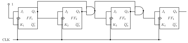
Drawn by us to help you understand the concept clearly, and verified to make sure it's accurate. For exams, practice from your textbook's own diagram.
Figure 10.7.1 shows a four-bit synchronous up-counter: FF1 is wired in toggle mode (), and AND gates feed to FF2, to FF3 and to FF4, with the same clock applied …
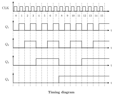
Drawn by us to help you understand the concept clearly, and verified to make sure it's accurate. For exams, practice from your textbook's own diagram.
This timing diagram (drawn above the logic diagram of Figure 10.7.1) plots CLK and – over the count 0–15, with toggling every pulse, at half that rate, at a quarter and $Q_4 …