Electronics · Ch 10 — Digital Electronics
Simplification of Boolean Expressions
Simplification of Boolean Expressions
A Boolean expression is the starting point for designing a combinational logic circuit. Before the circuit is built the expression is simplified so that it uses the minimum number of inputs and gates — a simpler circuit is cheaper, more reliable and more efficient. A Boolean expression written from a truth table takes one of two standard forms: sum of products (SOP) or product of sums (POS).
A product term is a logical AND of variables (e.g. ); a sum term is a logical OR of variables (e.g. ). An SOP expression is the ORing of product terms (e.g. ) and is realized by AND-OR logic or by universal NAND gates. A POS expression is the ANDing of sum terms (e.g. ) and is realized by OR-AND logic or by universal NOR gates.
Canonical form: minterms and maxterms
An expression is in canonical (standard) form when every term contains all the input variables. A minterm is a canonical product term (each variable appears once, complemented if it is 0 and un-complemented if it is 1); minterms are labelled m0, m1, m2, … A maxterm is a canonical sum term, labelled M0, M1, M2, … A non-canonical SOP or POS expression can be converted to canonical form by inserting the missing variable in the identity (for SOP) or (for POS) and expanding.
Karnaugh map (K-map)
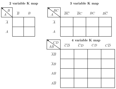
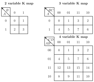
The Karnaugh map is a graphical, systematic method for simplifying Boolean expressions. It is a grid of cells, each cell representing one product-term (minterm) combination. For n input variables there are minterms, so the map has cells: a 2-variable map has 4 cells, a 3-variable map 8 cells and a 4-variable map 16 cells. The rows and columns are labelled in Gray-code order so that any two adjacent cells — horizontally, vertically or across opposite edges/corners — differ by only one bit; this is what makes grouping work.
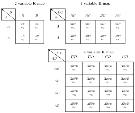
To plot an SOP expression, place a 1 in every cell whose minterm appears in the expression and 0s elsewhere. To plot a truth table, place a 1 in the cells corresponding to output 1s and 0s elsewhere.
Grouping: pairs, quads and octets
Simplification is done by grouping (looping) adjacent 1s into the largest possible groups of 2, 4 or 8:
- a pair (two adjacent 1s) eliminates one variable — the one that changes within the group;
- a quad (four adjacent 1s in a line or square) eliminates two variables;
- an octet (eight adjacent 1s) eliminates three variables.
Each reduction follows from Boolean algebra, e.g. for a pair .
Several rules make the groups as large, and hence the result as simple, as possible:
- Overlapping groups: the same 1 may be used in more than one group. Using 1s more than once gives larger groups and a simpler expression (e.g. with overlap versus without overlap ).
- Rolling the map: opposite edges are treated as adjacent — the top row rolls onto the bottom, the left column onto the right, and the four corners touch — so 1s on opposite edges can form pairs, quads or octets.
- Redundant groups: a group whose 1s are all already covered by other groups is redundant and must be removed before writing the final expression.
- Don't-care conditions: an input combination that can never occur, marked X, may be used as a 1 or a 0. Treating an X as 1 to enlarge a group yields a product term with fewer variables.
Realizing the simplified expression …
A Boolean expression is the key to designing a combinational logic circuit. It is simplified so the circuit uses the minimum number of inputs and gates, making it more reliable and efficient. An expression is written from a truth table as a sum o …
The ORing of ANDed variables — an OR of product terms, e.g. Y = A̅B + C̅A + AB. A product term is a logical AND of variables. SOP expressions are realized by AND-OR logic or by universal NAND gates. In an SOP each product term maps to one AND gate and the terms are ORed together, so it is the natu …
The ANDing of ORed variables — an AND of sum terms, e.g. Y = (A + B̅)(B + C)(A + B). A sum term is a logical OR of variables. POS expressions are realized by OR-AND logic or by universal NOR gates. In a POS each sum term maps to one OR gate and the terms are ANDed together, so it is the natur …
A canonical product (AND) term containing all the input variables, each appearing once — complemented if that variable is 0 and un-complemented if it is 1. Minterms are labelled m0, m1, m2, … A canonical …
A canonical sum (OR) term containing all the input variables. Maxterms are labelled M0, M1, M2, … A canonical POS expression is a product of maxterms. Each maxterm corresponds to one output-0 row of the truth table, with a variable un-complemented if it is 0 and complemented i …
| A | B | Product term | Minterm |
|---|---|---|---|
| 0 | 0 | A̅ B̅ | m0 |
| 0 | 1 | A̅ B | m1 |
| A | B | C | Product term | Minterm |
|---|---|---|---|---|
| 0 | 0 | 0 | A̅ B̅ C̅ | m0 |
| 0 | 0 | 1 | A̅ B̅ C | m1 |
| 0 | 1 | 0 | A̅ B C̅ | m2 |
| 0 | 1 | 1 | A̅ B C | m3 |
| 1 | 0 | 0 | A B̅ C̅ | m4 |
| 1 | 0 | 1 | A B̅ C | m5 |
A graphical, systematic method for simplifying Boolean expressions. It is a grid of cells, each representing one minterm combination; rows and columns are labelled in Gray-code order so adjacent cells (including opposite ed …
For n input variables the K-map has cells: 2 variables → 4 cells, 3 variables → 8 cells, 4 variables → 16 cells. Each extra variable doubles the number of minterms, and every minterm needs its own cell, so the map size grows as ; the cells are Gray-code ordered …
Drawn by us to help you understand the concept clearly, and verified to make sure it's accurate. For exams, practice from your textbook's own diagram.
K-map templates (p398-399): a 2×2 map (rows A̅, A; columns B̅, B), a 2×4 map (rows A̅, A; columns B̅C̅, B̅C, BC, BC̅) and a 4×4 map (rows A̅B̅, A̅B, AB, AB̅; columns C̅D̅, C̅D, CD, CD̅), with the axis var …
Drawn by us to help you understand the concept clearly, and verified to make sure it's accurate. For exams, practice from your textbook's own diagram.
Cell-numbering maps (p399): each cell holds its decimal minterm number. 4-variable map rows read 0,1,3,2 / 4,5,7,6 / 12,13,15,14 / 8,9,11,10 — the Gray-code ordering that keep …
Drawn by us to help you understand the concept clearly, and verified to make sure it's accurate. For exams, practice from your textbook's own diagram.
Minterm-per-cell maps (p400): each cell is labelled with both its product term and its minterm designation m0..m15, e.g. the 2-variable map holds A̅B̅ = m0, A̅B = m1, AB̅ = m2, AB = m3. What to notice: labelling each cell with its minterm lets you place a 1 wherever that minterm appears in the SOP e …
Grouping (looping) encircles adjacent 1s into the largest groups. A pair (two adjacent 1s) eliminates one variable; a quad (four adjacent 1s in a line or square) eliminates two variables; an octet (eight adjacent 1s) eliminates three va …
A group of adjacent 1s eliminates k variables: pair → 1 variable, quad → 2 variables, octet → 3 variables. Example (pair): . The eliminated variables are exactly those that change within the group; the variables that stay cons …
While encircling groups the same 1 may be used in more than one grouping. Using 1s more than once produces larger groups and a simpler expression — e.g. with overlapping Y = D + BC, …
Encircling groups by treating opposite edges of the map as adjacent: the top row rolls onto the bottom, the left column onto the right, and all four corners touch. Rolling can form pairs, quads or o …
A group in which all the 1s are already covered (overlapped) by other groups. A redundant group must be eliminated before writing the simplified Boolean equation, giving a simpler logic circuit. Spotting and removing redundant groups keeps the final SOP expression minimal, so the rea …
An input combination that can never occur; marked X in the truth table and K-map. An X may be treated as a 1 or a 0, and using it as a 1 to enlarge a group yields a product term with fewer variables. Example: without the don't-cares …
Drawn by us to help you understand the concept clearly, and verified to make sure it's accurate. For exams, practice from your textbook's own diagram.
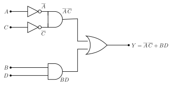
Figure 10.4.1: A and C are inverted; and feed an AND gate giving ; B and D feed a second AND gate giving BD; the two AND outputs feed an OR gate giving . This realizes the K-map simplif …
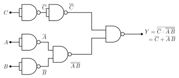
Drawn by us to help you understand the concept clearly, and verified to make sure it's accurate. For exams, practice from your textbook's own diagram.
Figure 10.4.2: each product term is formed by a NAND gate and the outputs are combined by a final NAND gate, realizing . It shows how AND-OR logic is converted to NAND-NAND logic by replac …