Electronics · Ch 3 — Transistor Amplifiers
General Parameters of Amplifiers
General Parameters of Amplifiers
BJT amplifiers are built in one of three configurations — CB, CC or CE — chosen for a particular application on the basis of their characteristic parameters. To select the right amplifier we must know these general parameters. Consider the general representation of an amplifier (Figure 3.2.1) with AC input voltage v_i and current i_i, and AC output voltage v_o and current i_o. Amplifiers are described by five characteristic parameters together with their bandwidth.
Gain and impedance parameters
- Current gain (A_i) — the ratio of output current to input current: .
- Voltage gain (A_v) — the ratio of output voltage to input voltage: .
- Power gain (A_p) — the ratio of output power to input power: . Power gain also equals the product of voltage gain and current gain: .
- Input impedance (Z_i) — the ratio of input voltage to input current: .
- Output impedance (Z_o) — the ratio of output voltage to output current: .
Bandwidth
The frequency response of an amplifier (Figure 3.2.2) is a plot of its voltage gain against frequency. The difference between the higher and lower cut-off frequencies is called the bandwidth: . At the cut-off frequencies f_H and f_L the voltage gain equals (or exceeds) 70.7% of its maximum value; these are also called the half-power frequencies, because the power delivered at them is half of its maximum.
On this page the body text of the source book refers to this graph as 'Figure 3.3.2', but the figure is captioned Figure 3.2.2 and belongs to this section (3.2, General Parameters of Amplifiers). The correct reference is Figure 3.2.2.
Half-power frequency (3 dB frequency)
The lower and upper cut-off frequencies f_L and f_H are also called 3 dB or half-power frequencies. When the voltage falls to (0.707) of its maximum value, the power — which is proportional to the square of the voltage — falls to of its maximum. The name '3 dB' comes from the fact that the voltage gain at these frequencies is 3 dB below the maximum. For distortionless amplification the signal's frequency range must lie within the amplifier's bandwidth.
Decibel gain
The gain of an amplifier is simply a number, but for practical importance it is given the unit bel or decibel. The power gain in bel is the common (base-10) logarithm of the power gain:
where P_i and P_o are the input and output powers. The bel is a large unit, so the decibel (dB) — one-tenth of a bel — is used in practice. Since power is proportional to the square of the voltage,
…
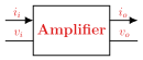
Drawn by us to help you understand the concept clearly, and verified to make sure it's accurate. For exams, practice from your textbook's own diagram.
Reproduces textbook Figure 3.2.1. A single amplifier block with the AC input quantities (voltage v_i, current i_i) entering on the left and the AC output quantities (voltage v_o, current i_o) leaving on the right. It defines the four quantities from which the current gain, voltage gai …
Current gain ; voltage gain ; power gain ; input impedance ; output impedance . Here i_i, i_o are the AC input/output currents (amperes) and v_i, v_o the AC voltages (volts), so the three gains are pure numbers while Z_i and Z_ …
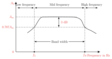
Drawn by us to help you understand the concept clearly, and verified to make sure it's accurate. For exams, practice from your textbook's own diagram.
Reproduces textbook Figure 3.2.2. Voltage gain A_v is plotted against frequency; the gain is flat at its maximum Am across the mid-frequency band and rolls off in the low- and high-frequency regions. The lower and upper cut-off frequencies f_L and f_H, where the gain has dropped by 3 dB to 0.707 Am, mark the edges of the bandwidth. (The source book's body text …
The bandwidth is the range of frequencies between the upper and lower cut-off frequencies: . At f_H and f_L the voltage gain is 70.7% of its maximum (the h …
In decibels the gain is , so the voltage gain in dB is and the current gain in dB is . The decibel is one-tenth of a bel, where the po …