Electronics · Ch 3 — Transistor Amplifiers
Introduction to Amplifiers
Introduction to Amplifiers
An amplifier is a device that receives a small electrical signal and enlarges it; the process of increasing the strength of a weak electrical signal is called amplification. A transistor amplifier is a circuit that increases the strength of a weak input signal — its voltage, current or power — without changing its frequency. It is made of one or more transistors together with a few passive components (resistors and capacitors) and a DC biasing arrangement. Many kinds of transistors — BJTs, FETs and others — are used for amplification.
Amplifiers appear at almost every stage of an electronic system. A radio receiver amplifies antenna signals of a few microvolts up to volts, enough to drive a loudspeaker and fill a room with sound; a microphone's few-millivolt signal is amplified to drive speakers in an auditorium. A pre-amplifier raises a signal just enough for a following stage to accept it, while a power amplifier enlarges it enough to power a loudspeaker.
DC biasing conditions for a BJT amplifier
For normal operation a BJT amplifier must be biased so that the transistor works in the active region of its output characteristics. Two conditions must be satisfied:
- the base-emitter junction must be forward biased, with a forward voltage of about 0.6 V-0.7 V for silicon and 0.2 V-0.32 V for germanium;
- the base-collector junction must be reverse biased within its maximum limit, with the operating point (Q-point) normally fixed at the centre of the DC load line.
Once these static (DC) conditions are established, the weak AC signal is applied to the input to obtain a strong output.
Faithful amplification
Fixing the operating point alone is not enough; the operating point must not shift into cut-off or saturation while the signal swings. Ideally only the magnitude of the signal should increase, with no change in its shape — that is, no change in frequency or type of waveform. The process of increasing the strength of a signal without any change in its shape is called faithful amplification (Figure 3.1.1). Three basic conditions must be met for faithful amplification:
- proper zero-signal collector current;
- a minimum base-emitter voltage V_BE at every instant;
- a minimum collector-emitter voltage V_CE at every instant.
Classification of amplifiers
Amplifiers are classified under several criteria according to how they are used — the input-signal level, the nature of the output, the operating frequency range, the position of the operating point, the configuration, the coupling method, the number of stages and the bandwidth. The table below summarises these criteria together with typical application areas.
Concept of working of an amplifier
An amplifier can be pictured as a block with a low input impedance and a high output impedance (Figure 3.1.2); the DC bias is left out of the picture so that only the amplification is shown. When an AC signal is applied, the AC current flows through the small input impedance Z_in, so the input voltage is . A current of nearly the same size flows through the high output impedance Z_o and develops a much larger voltage . Thus the small input signal appears in amplified form at the output.
The behaviour depends on the configuration. Input impedance is low in CB and moderate in CE; output impedance is high in CB and moderate in CE. As a result:
- a CB amplifier gives voltage amplification but no current amplification, since I_E is approximately equal to I_C;
- a CE amplifier gives both voltage and current amplification, since I_C is greater than I_B;
- a CC amplifier, having high input resistance and low output resistance, gives no voltage amplification but does give current amplification, since I_E is greater than I_B.
For example, a 25 mV microphone signal fed to a CB amplifier with a low input impedance and a much higher collector-load impedance is transferred from the low-resistance input to the high-resistance output, giving a voltage amplification of about 200 while the emitter and collector currents stay nearly equal (I_E is approximately equal to I_C) — voltage amplification with no current amplification. This worked example is illustrated in Figure 3.1.2a.
In the source book this worked example prints the input impedance as '25W' and the collector load as '5kW'; the 'W' is a misprint for the ohm symbol, so these values are actually 25 Ω and 5 kΩ. Also, Figure 3.1.2a labels the output impedance as Z_o = 100 Ω, while the accompanying calculation uses the 5 kΩ collector load to obtain the 5 V output. The value that makes the calculation work is 5 kΩ.
Small-signal and large-signal amplifiers
Based on the level of the input signal, linear amplifiers are classified as small-signal and large-signal amplifiers.
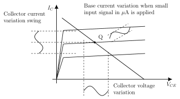
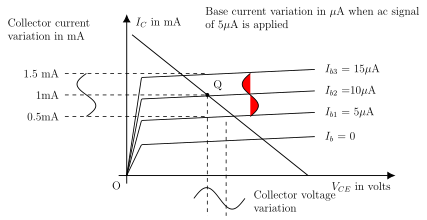
Small-signal amplifiers (voltage amplifiers) are designed to amplify small AC input signals and are used in the initial stages of a system, such as radio and TV receivers and measuring instruments. An input whose amplitude is smaller than the Q-point values is a small signal, and the Q-point lies well within the active region (Figure 3.1.3). Their primary job is voltage amplification with the largest possible gain; their power-handling capacity and efficiency are low. The few-millivolt signals from a microphone, a CD/DVD head or a receiver antenna are examples of small signals. On the CE output characteristics (Figure 3.1.4), with no input signal the base current might be 10 μA and the collector current 1 mA; when a 5 μA AC signal is applied, the base current swings between 5 μA and 15 μA and the collector current swings between 0.5 mA and 1.5 mA.
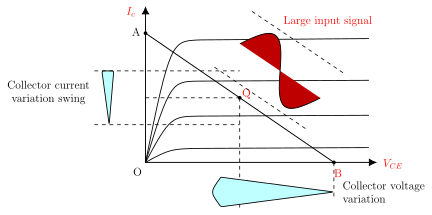
Large-signal amplifiers (power amplifiers) are designed to handle large input signals and to deliver enough power to drive a loudspeaker, a CRT or another power device. Their main features are power efficiency, the maximum power they can handle, and impedance matching to the output device. An input whose amplitude is larger than the Q-point values is a large signal (Figure 3.1.5). A power amplifier follows the voltage amplifier and forms the last (driver) stage; such amplifiers are used in radio and TV transmitters and receivers. …
Amplification is the process of increasing the strength of a weak electrical signal. The device that does this is an amplifier — it receives a small electrical signal and enlarge …
A transistor amplifier is a circuit that increases the strength of a weak input signal (voltage, current or power) without changing its frequency. It consists of one or more transistors together with a few passive c …
Faithful amplification is the process of increasing the strength of a signal without any change in its shape — no change in frequency or type of waveform, only the magnitude increases. It requires a proper zero-signal collector current and a minimum base-emitter voltage V_BE an …
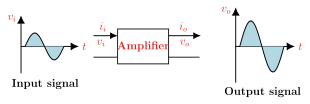
Drawn by us to help you understand the concept clearly, and verified to make sure it's accurate. For exams, practice from your textbook's own diagram.
Reproduces textbook Figure 3.1.1. A small-amplitude input sine wave (input voltage v_i versus time) feeds an amplifier block, which delivers a larger-amplitude output sine wave (output voltage v_o versus time) of exactly the same shape and frequency. It visualises faithful amplification — the output …
| Criterion | Classification | Applications |
|---|---|---|
| 1. Input signal | Small signal amplifier | Voltage amplifiers |
| Large signal amplifier | Power amplifiers | |
| 2. Nature of output | Voltage amplifier | Voltage amplifications |
| Power amplifier | Power amplifications | |
| 3. Frequency range | AF amplifiers | Audio equipments |
| IF amplifiers | Radio circuits | |
| RF amplifiers | AM broadcasting | |
| VHF amplifiers | FM broadcasting | |
| UHF amplifiers | TV, military communications like mobiles, radar | |
| SHF amplifiers | Satellite communication | |
| 4. Operating point | Class A | Voltage amplifications |
| Class B | Power amplifications | |
| Class C | Power amplifications | |
| 5. Configuration | CE amplifier | Audio amplifiers |
| CB amplifier | High frequency applications | |
| CC amplifier | As an impedance matching circuit | |
| 6. Coupling | RC coupled | Multistage AF applications |
| Transformer coupled | RF amplifier | |
| Direct coupled | DC amplifiers |
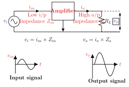
Drawn by us to help you understand the concept clearly, and verified to make sure it's accurate. For exams, practice from your textbook's own diagram.
Reproduces textbook Figure 3.1.2. The amplifier block carries a low input impedance Z_in and a high output impedance Z_o and drives a load resistor R_L; the DC bias is deliberately omitted so only the amplification is shown. The input current i_in produces v_i = i_in x Z_in across the small input impedance, while a nearly equal output current i_o produces the larger v_o = i_o x Z_o across the high outpu …
Across the low input impedance the input voltage is , and across the high output impedance the output voltage is . Because Z_o is much larger than Z_in while the currents are nearly equal, v_o is mu …
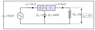
Drawn by us to help you understand the concept clearly, and verified to make sure it's accurate. For exams, practice from your textbook's own diagram.
Reproduces textbook Figure 3.1.2a. A 25 mV microphone signal drives the emitter (E) of a common-base amplifier; with input current i_E = 1 mA through the input impedance and nearly equal collector current i_C flowing through the collector load, the output is 5 V, giving a voltage amplification of about 200 with I_E approximately equal to I_C. Note that the figure's printed labels ('25W', '5kW', Z_o = 100 Ω) contain the misprints described in the section body — the 25 …
A small-signal amplifier is designed to amplify a small AC input signal whose amplitude is smaller than the transistor's Q-point values, with the Q-point kept in the active region. Its primary function is voltage amplification with the largest possible gain, so it is also called a voltage amplifier; its power-handling capacity and efficiency are low. Such amplif …
Drawn by us to help you understand the concept clearly, and verified to make sure it's accurate. For exams, practice from your textbook's own diagram.
Reproduces textbook Figure 3.1.3. On the CE output characteristic (collector current Ic versus V_CE) the Q-point sits in the active region on the DC load line. A small base-current variation produces a small sinusoidal collector-current swing and a small collector-voltage swing, …
Drawn by us to help you understand the concept clearly, and verified to make sure it's accurate. For exams, practice from your textbook's own diagram.
Reproduces textbook Figure 3.1.4. The family of CE output curves (Ib = 0, 5 μA, 10 μA, 15 μA) carries a DC load line and a Q-point at 1 mA (Ib = 10 μA). When a 5 μA AC signal is applied the base current swings from 5 μA to 15 μA and the collector current swings from 0.5 mA to 1.5 mA — a concrete picture …
A large-signal amplifier is designed to handle a large input signal whose amplitude is larger than the transistor's Q-point values, and to deliver enough power to drive a loudspeaker, CRT or other power device. Its key features are power efficiency, maximum power handling and impedance matching to the load, so it is also called a power amplifier …
Drawn by us to help you understand the concept clearly, and verified to make sure it's accurate. For exams, practice from your textbook's own diagram.
Reproduces textbook Figure 3.1.5. With the Q-point at the centre of the DC load line (from point A on the Ic axis to point B on the V_CE axis), a large input signal drives large collector-current and collector-voltage swings that use almost the full length of the load line — the defi …
Drawn by us to help you understand the concept clearly, and verified to make sure it's accurate. For exams, practice from your textbook's own diagram.
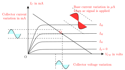
Reproduces textbook Figure 3.1.6. The Q-point lies at the centre of the DC load line, so the base current, collector current and collector voltage all vary sinusoidally and symmetrically and the output faithfully resembles the input — Case (i …
Drawn by us to help you understand the concept clearly, and verified to make sure it's accurate. For exams, practice from your textbook's own diagram.
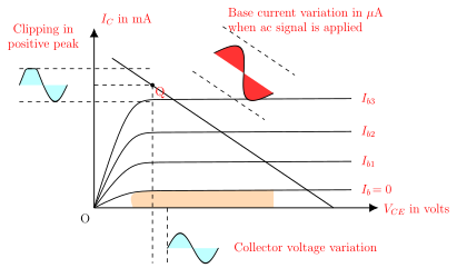
Reproduces textbook Figure 3.1.7. With the Q-point near the saturation region, the positive half cycle drives the transistor into saturation; the collector current holds at its saturation value and the output is clipped at its positive peaks — Case (ii), d …
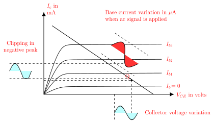
Drawn by us to help you understand the concept clearly, and verified to make sure it's accurate. For exams, practice from your textbook's own diagram.
Reproduces textbook Figure 3.1.8. With the Q-point near the cut-off region, the negative half cycle drives the transistor into cut-off; the collector current holds at its cut-off value and the output is clipped at its negative peaks — Case (iii), di …