Solved Examples · Example 3
Q.Find the end points of the load line for the circuit given figure 2.1.11.
Karnataka PUCTextbookNumericImportance★★★★★est
23% · 11/47 Questions
You're viewing a preview — the full solution, concept, methods & PYQ mapping are locked.
Start your 14-day free trial to unlock the full solution →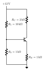
[!TLDR]
The load line joins on the x-axis to on the y-axis.
In a voltage divider bias circuit the emitter resistor appears in the collector loop, so Kirchhoff's voltage law around that loop gives
The two end points of the DC load line come from setting each variable to zero.
x-axis point (cutoff), :
y-axis point (saturation), : …
Unlock everything free for 14 days
- Full step-by-step solutions
- Concept-first explanations
- Methods, shortcuts & mistakes
- PYQ mapping + timed mock tests
Full access for 14 days. No credit card required.