Solved Examples · Example 4
Q.Find the Q point for the circuit of figure 2.1.11 considering transistor to be of silicon.
Karnataka PUCTextbookNumericImportance★★★★★est
34% · 16/47 Questions
You're viewing a preview — the full solution, concept, methods & PYQ mapping are locked.
Start your 14-day free trial to unlock the full solution →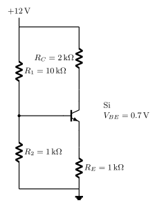
[!TLDR]
The operating point is .
The Q point (quiescent/operating point) is the zero-signal point on the load line, with coordinates . For voltage divider bias it is computed from the potential-divider output voltage across .
Divider voltage:
Quiescent collector current (with and silicon ):
Quiescent collector-to-emitter voltage:
…
Unlock everything free for 14 days
- Full step-by-step solutions
- Concept-first explanations
- Methods, shortcuts & mistakes
- PYQ mapping + timed mock tests
Full access for 14 days. No credit card required.