Electronics · Ch 7 — Wireless Communication
Introduction
Introduction
Communication is simply the process of exchanging information. Human beings have communicated since the very beginning of mankind, using speech, gestures and writing to share their thoughts, ideas and feelings. Early communication — whether verbal or non-verbal — faced two big barriers: language and distance.
The barrier of distance began to fall once electricity and its applications were understood in the nineteenth century. The invention of the telegraph in 1844, the telephone in 1876 and the discovery of radio in the 1880s each pushed the electronic communication system a giant step forward. Today, familiar systems such as the telephone and cell phone, radio, television and the internet let us share information almost instantly.
Depending on the medium used, electronic communication can take place as line or wire communication, radio (wireless) communication, satellite communication or Optical Fibre Communication (OFC).
Electronic communication system
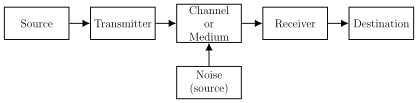
Every communication system, however simple or complex, can be drawn as the same basic chain of blocks (see Figure 7.1). The information starts at a source, is prepared for the channel by a transmitter, travels through the channel where noise is added, and is finally recovered by a receiver for the destination.
- Source — generates the message, which is variously called the information, intelligence, signal or data.
- Transmitter — a circuit that processes the message and sends it out effectively over the channel.
- Channel / medium — the path through which the information flows (a wire, free space, an optical fibre, and so on).
- Receiver — picks up the signal from the channel and processes the information into a form suitable for the destination.
- Destination — the end user for whom the information is meant.
- Noise — any unwanted electrical disturbance that gets added to the message inside the communication channel.
Noise
Noise is any unwanted electrical energy that tends to interfere with the easy and correct reception and reproduction of the wanted signal. Noise is random in nature and may arise inside a system (internal) or come from outside it (external). An important practical fact is that noise can be minimised but can never be completely eliminated.
The amount of noise in a system is described using parameters such as the signal-to-noise ratio (SNR), the noise figure (NF) and the noise temperature.
The signal-to-noise ratio (SNR) is the ratio of the signal power to the noise power at any point in a circuit:
For good reception the signal power should be as large as possible and the noise power as small as possible (ideally zero), which would make the SNR tend to infinity. In real circuits the SNR usually lies in the range of about 10 to 50 dB.
The noise ratio (NR) compares the signal-to-noise ratio going into a system with the ratio coming out of it:
If a system adds no noise of its own, the output SNR equals the input SNR and the noise ratio is 1 — the ideal case. If the system generates its own noise, the output SNR becomes smaller and the noise ratio becomes greater than 1.
When the noise ratio is expressed in decibels it is called the noise figure (NF):
Re-arranging this relation lets us find the noise ratio from a known noise figure: .
Frequency of radio waves
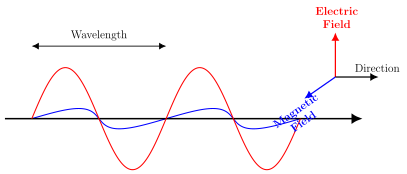
Before a message can be transmitted through space, the information must first be turned into electrical signals that suit the medium. Signals that can radiate out into space in this way are called electromagnetic waves (e.m. waves), also known as radio frequency (RF) waves, and they are able to travel long distances. …
Drawn by us to help you understand the concept clearly, and verified to make sure it's accurate. For exams, practice from your textbook's own diagram.
Reproduces the layout of Figure 7.1: five blocks connected left to right — Source, Transmitter, Channel or Medium, Receiver, Destination — with a separate Noise (source) block feeding upward into the channel. It shows at a glance how a message flows from source to …
The signal-to-noise ratio is the ratio of signal power to noise power at any point in a circuit. A larger SNR means a cleaner signal; practical v …
The noise ratio compares the SNR entering a system with the SNR leaving it. For an ideal, noiseless system ; a system that a …
The noise figure is the noise ratio expressed in decibels. It can be inverted to recover the noise ratio: . Here is the dimensionless noise ratio and the result is in decibels. A noiseless system has , so dB; a larger NF means …
Drawn by us to help you understand the concept clearly, and verified to make sure it's accurate. For exams, practice from your textbook's own diagram.
Illustrates Figure 7.1.2: a sinusoidal electric field and a sinusoidal magnetic field oscillating at right angles to each other and to the direction of travel, with the wavelength marked across one full cycle. It shows why an e.m. (radio-frequency) wave is a transver …