Electronics · Ch 7 — Wireless Communication
Propagation of radio waves
Propagation of radio waves
Propagation refers to the forward travel of radio waves from the transmitter to the receiver. After leaving the transmitting antenna, a radio wave can reach the receiver by one of three basic paths:
- (a) the ground wave,
- (b) the space wave, and
- (c) the sky wave.
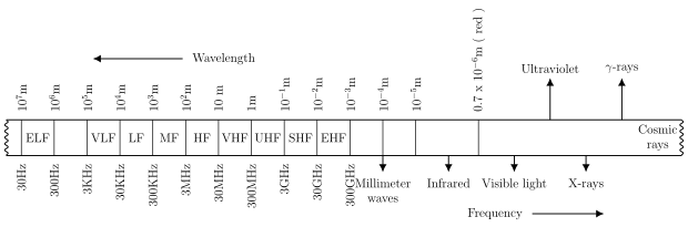
The complete electromagnetic spectrum is shown in Figure 7.2, and Table 7.2 classifies the various radio-frequency bands together with the services that use each of them. Which path a signal takes depends mainly on its frequency band.
Troposphere
The troposphere is the layer of atmosphere lying immediately on the surface of the earth. It holds roughly 75% of the total gaseous mass of the atmosphere and almost all of its moisture, dust particles and winds. It reaches up to an average altitude of about 15 km, and most ground-wave and space-wave communication takes place within it.
(a) Ground waves
A radio wave that is transmitted along, or reflected from, the surface of the earth is called a ground wave or surface wave. Ground waves use the earth itself as a kind of transmission line. The direction of the electric field — horizontal or vertical — decides the polarization of the e.m. wave; a vertically polarized wave, one whose electric field is perpendicular to the earth's surface, can propagate as a ground wave.
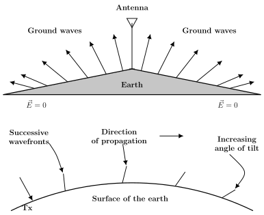
The LF and MF bands travel by ground-wave propagation, covering distances from a few hundred to a few thousand kilometres at these low frequencies. As the wave moves over the earth's surface its strength steadily falls, because energy is absorbed by the earth, until finally the electric field is reduced to zero (Figure 7.3).
The conductivity of the earth's surface increases with dampness or wetness — a water surface conducts better than dry land — so ground-wave propagation is especially useful in marine communication, that is, ship-to-shore and shore-to-ship links.
(b) Space waves
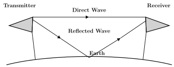
Space waves, also called line-of-sight waves, are very useful in VHF propagation. The direct wave together with the ground-reflected wave are jointly called the space wave (Figure 7.4). …
Drawn by us to help you understand the concept clearly, and verified to make sure it's accurate. For exams, practice from your textbook's own diagram.
Corresponds to Figure 7.2: a horizontal frequency axis showing wavelengths from about m down to m and beyond, the radio bands (ELF, VLF, LF, MF, HF, VHF, UHF, SHF, EHF) with frequencies from 30 Hz up to 300 GHz, and the higher-frequency regions (infrared, visible light, ultraviolet, X-rays, gamma and cosmic rays). It places …
| Frequency | Name of the frequency band | Uses |
|---|---|---|
| 3 – 30 KHz | Very Low Frequency (VLF) | Long distance point to point communication |
| 30 KHz – 300 KHz | Low Frequency (LF) | Navigation services |
| 300 KHz – 3 MHz | Medium Frequency (MF) | Radio broadcasting, ship to shore communication, Police (walkie-talkie) |
| 3 MHz – 30 MHz | High Frequency (HF) | International broadcasting, telephone, aviation, all classes of communication |
| 30 MHz – 300 MHz | Very High Frequency (VHF) | RADAR, TV, FM broadcasting, short distance communication |
| 300 MHz – 3 GHz | Ultra High Frequency (UHF) | TV, RADAR, aviation |
Drawn by us to help you understand the concept clearly, and verified to make sure it's accurate. For exams, practice from your textbook's own diagram.
Reproduces Figure 7.3. The upper part shows ground waves spreading from a vertical antenna and bending along the earth's curvature, with the field reduced to at the far ends; the lower part shows successive wavefronts tilting more and more as they lose energy to the earth. It e …
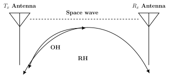
The radio horizon (RH) is about four-thirds of the optical horizon (OH), because radio waves bend slightly around the earth and so reach a little farther than the naked eye can see; for the earth …
Drawn by us to help you understand the concept clearly, and verified to make sure it's accurate. For exams, practice from your textbook's own diagram.
Corresponds to Figure 7.4: a direct wave travels straight from the transmitting antenna to the receiving antenna, while a second path reflects off the earth; together they form the space wav …
Drawn by us to help you understand the concept clearly, and verified to make sure it's accurate. For exams, practice from your textbook's own diagram.
Reproduces Figure 7.5: the straight space-wave path between the Tx and Rx antennas, with two curved arcs marking the optical horizon (OH) and the farther radio horizon (RH). It shows visually that radio wa …