Physics · Ch 13 — AC Circuits
AC Generator
AC Generator
An AC generator works by rotating a coil inside a magnetic field (or, equivalently, rotating a magnet near a stationary coil), so that the magnetic flux linked with the coil changes continuously and sinusoidally with time, inducing an emf that also varies sinusoidally: , where is the peak (maximum) value of the emf and is the angular frequency of the coil's rotation, f being the frequency of rotation (and hence of the generated emf) in hertz.
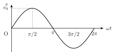
When this emf is applied across any circuit, the resulting current also varies periodically with the same angular frequency , but in general it need not reach its own zero, minimum and maximum values at exactly the same instants as the emf does -- there can be a constant phase difference between the two, so the current takes the general form , where is the peak current. Exactly what this phase difference turns out to be -- zero, a lag of , a lead of , or something in between -- depends entirely on what the circuit contains (a pure resistor, a pure inductor, a pure capacitor, or some combination), and working this out for each case is the central task of sections 13.5 onward. The graph of e (or, identically in shape, of i) against is a smooth sine curve that crosses zero, rises to , f …
Drawn by us to help you understand the concept clearly, and verified to make sure it's accurate. For exams, practice from your textbook's own diagram.
What this figure shows. A single smooth sinusoidal curve of instantaneous emf e plotted on the vertical axis against (in radians) on the horizontal axis, starting at the origin (e = 0 at ), rising to a maximum of at , returning to zero at , falling to a minimum of at , and returning to zero again at , completing one full cycle. The curve visually establishes that the emf reverses its sign (direction) after every half revolution/half cycle of the generator coil -- the defining feature of an alternating emf -- with the peak value m …
Worked out. An alternating voltage is given as (volt, with t in seconds). Comparing directly with the standard form gives the peak value V immediately by inspection. Matching with gives , so the frequency is Hz, and the time period follows as s. Finally, the instantaneous value of the voltage at s is found by direct substitution: V. This example fixes the pattern used throughout the chapter: read and straight off a given sinusoidal expression by comparison with the standard form, befo …