Physics · Ch 13 — AC Circuits
Phasors
Phasors
The mathematics of adding several alternating quantities that are out of phase with each other (for example, the separate voltage drops across a resistor, an inductor and a capacitor all carrying the same AC current) becomes much simpler if each sinusoidally-varying quantity is represented, not as a plain number, but as a rotating VECTOR of fixed length -- called a phasor.
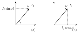
A phasor representing a quantity like (or ) is drawn as an arrow of length equal to the quantity's own PEAK value ( or ), anchored at the origin and rotating anticlockwise at a constant angular speed equal to , the same angular frequency as the AC itself. At any instant, the arrow makes some angle with a fixed reference axis (conventionally the horizontal), and the INSTANTANEOUS value of the quantity is recovered as the projection of this rotating arrow onto a chosen fixed axis: for a quantity written in sine form, the projection is taken on the vertical (Y) axis; for a quantity written in cosine form, the projection is instead taken on the horizontal (X) axis. Because every phasor in a given circuit rotates at the exact same angular speed , the ANGLE between any two phasors stays fixed throughout the motion, equal to the phase difference between the two quantities they repres …
Drawn by us to help you understand the concept clearly, and verified to make sure it's accurate. For exams, practice from your textbook's own diagram.
What this figure shows. Two side-by-side phasor diagrams, each showing a fixed horizontal reference axis (OX) and a rotating arrow (the phasor) of length equal to the peak value, anchored at the origin O and rotating anticlockwise at angular speed . In diagram (a), for quantities written in SINE form ( or ), the phasor is shown at an angle from OX, with a dashed perpendicular line dropped from the phasor's tip down onto the VERTICAL (Y) axis, showing that the instantaneous value is the phasor's projection on the Y-axis. In diagram (b), for quantities written in COSINE form ( or ), the same rotating phasor is instead projected onto the HORIZONTAL (X) axis, with the dashed perpendicular dropped down onto OX. Both diagrams establish that the phasor's own length never changes …