Physics · Ch 9 — Current Electricity
Galvanometer as a Voltmeter
Galvanometer as a Voltmeter
Turning a moving-coil galvanometer into a voltmeter -- an instrument for measuring potential difference, connected in PARALLEL with the part of the circuit across which the voltage drop is to be measured -- again needs three things done together, but this time in the OPPOSITE sense to the ammeter conversion. First, the instrument's voltage-measuring capacity must be raised to the desired higher value. Second, its effective resistance must be INCREASED, not decreased: since connecting a low-resistance galvanometer directly across two points would draw some current (because of its comparatively low native resistance) and so reduce the very potential difference being measured, an IDEAL voltmeter should instead have as close to INFINITE resistance as possible. Third, the coil must be protected from damage from any excessive applied potential difference.
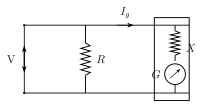
All three requirements are met by connecting a suitably high resistance X in SERIES with the galvanometer (the opposite arrangement to the ammeter's parallel shunt), and then connecting this whole series combination across the two points whose potential difference is to be measured. If V is the voltage to be measured and the current through the galvanometer at full-scale deflection, then V splits across the two series elements,
which rearranges to give the series resistance required:
used directly in Ex. 9.9, where a 25 A, 25 \Omega galvanometer is converted to a 0-10 V voltmeter (giving k\Omega), and in Ex. 9.10, where the very same base galvanometer (40 \Omega, 4 mA) is converted separately into BOTH a 0-0.4 A ammeter (via a parallel shunt, Section 9.5.1) and a 0-0.5 V voltmeter (via a series resistance, this section) -- a compact illustration that the ammeter and voltmeter conversions are two independent, interchangeable modifications of the exact same underlying instrument.
If is defined as the factor by which the voltage range is increased over the galvanometer's own native full-scale voltage , Eq. (9.14) can equivalently be written as -- exactly parallel in form to the ammeter's result, underlining how closely related the two conversions are, differing only in whether the added resistance goes in series (high, for a voltmeter) or in parallel (low, for an ammeter). …
Drawn by us to help you understand the concept clearly, and verified to make sure it's accurate. For exams, practice from your textbook's own diagram.
What this figure shows. A moving-coil galvanometer of resistance G and full-scale deflection current , with a high resistance X connected in SERIES with it (not in parallel, unlike the ammeter conversion), and this whole series combination connected directly ACROSS the two points between which the potential difference V is to be measured. The figure sets up , so that at full-scale deflection the applied voltage V splits between the added series resistance X and the galvanometer coil's own resistance G, giving as the resistance that mu …
Worked out. A galvanometer with resistance and full-scale deflection current is to read voltages from 0 to 10 V. Using with V: k\Omega -- a very large series resistance, as expected, since it is what keeps the total voltmeter resistance high (close to itself) so the meter draws only a tiny current even at the top of its 10 V range. …
Worked out. A galvanometer of resistance needs a current of mA for full-scale deflection, and the problem asks for the modification needed to turn it into (a) an ammeter reading 0 to 0.4 A and (b) a voltmeter reading 0 to 0.5 V, done as two separate, independent conversions of the same base galvanometer. For (a), the ammeter shunt is , connected in PARALLEL with the coil. For (b), the voltmeter series resistance is , connected in SERIES with the coil. The pair of results is a compact illustration of how the SAME galvanometer becomes either instrument, purely by choosing parallel-and-low versu …
Property | Ammeter | Voltmeter
What it measures | Current | Potential difference
How it is connected | In series with the circuit element | In parallel with the circuit element
What it fundamentally is | A moving-coil galvanometer with a low shunt resistance added in parallel (ideal resistance: zero) | A moving-coil galvanometer with a high resistance added in series (ideal resistance: infinite)
How its range/sensitivity behaves | Smaller the shunt resistance, greater the current it can measure | Larger its series resistance, greater the potential difference it can measure …