Physics · Ch 9 — Current Electricity
Galvanometer as an Ammeter
Galvanometer as an Ammeter
Turning a moving-coil galvanometer (MCG) into an ammeter -- an instrument for measuring current, connected in SERIES with the part of the circuit whose current is to be measured -- needs three things done at once. First, the instrument's effective current-carrying capacity must be raised to whatever higher value the ammeter is meant to read up to. Second, its effective resistance must be LOWERED: the galvanometer's own finite coil resistance G, if left in series unmodified, would itself reduce the very current in the external resistance R that is being measured, whereas an IDEAL ammeter should have zero resistance and disturb the circuit not at all. Third, the delicate coil must be protected from damage by any excessive current.
All three requirements are met at once by connecting a LOW resistance, called the shunt (S), in PARALLEL with the galvanometer. The shunt serves several purposes together: it diverts most of the total current away from the sensitive coil and along this alternative low-resistance path, protecting the instrument from damage; it thereby extends the effective RANGE of currents the ammeter can measure; and, since a low resistance placed in parallel with the (comparatively higher) coil resistance always lowers the combination's net resistance, it also satisfies the 'as close to zero resistance as possible' requirement of an ideal ammeter.
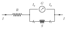
Because the galvanometer (resistance G) and the shunt (resistance S) are connected in parallel, they share the same potential difference across their common ends. If is the current through the galvanometer and is the current diverted through the shunt (with I the total current entering the ammeter), then equal potential differences across the two parallel branches gives
This one equation is enough to calculate the shunt needed for any desired current range, in two equivalent ways.
(i) If the desired full-scale reading I is to be n times the galvanometer's own full-scale current, i.e. , substituting into Eq. (9.13) gives
the shunt required to multiply the galvanometer's own range by a factor n -- used directly in Ex. 9.7, converting a 100 A, 100 \Omega galvanometer to a 10 mA ammeter (, ). …
Drawn by us to help you understand the concept clearly, and verified to make sure it's accurate. For exams, practice from your textbook's own diagram.
What this figure shows. A moving-coil galvanometer of resistance G and full-scale current , with a low shunt resistance S connected directly in PARALLEL across its two terminals, and this parallel combination in turn connected in SERIES with the external resistance R through which the actual current I to be measured flows. Since G and S are in parallel and share the same potential difference across their common ends, the figure sets up the relation (with the current diverted through the shunt), i.e. of the total current I entering the ammeter, only the small fraction passes t …
Worked out. A galvanometer with coil resistance and full-scale deflection current mA is to be converted into an ammeter reading 0 to 10 mA. Writing the desired range as gives the multiplying factor , and substituting into the shunt formula (the algebraically simplified form of for this exact case) gives -- a small shunt resistance, comfortably below the galvanometer's own 100 \Omega, so that almost all of the 10 mA to be measured is diverted safely around the sensitive coil and only its native 0.1 mA passes through the coil …
Worked out. A galvanometer of resistance is to be shunted so that only 20% of the total current I entering the combination passes through the galvanometer itself, i.e. , with the remaining 80% (=) diverted through the shunt S. Since G and S carry the same voltage in parallel, gives -- independent of the actual numeric value of the total current I itself, since it cancels out of the ratio, leaving the shunt value determined purely by the desired current-SPLIT fraction and the galvanometer's ow …