Physics · Ch 9 — Current Electricity
Kirchhoff's Voltage Law
Kirchhoff's Voltage Law
Kirchhoff's second law -- the voltage law -- states that around any closed loop of an electrical network, the algebraic sum of every product of current and resistance (every 'IR' potential drop) together with every emf encountered is zero:
Getting the correct sign for each term needs two separate conventions, one for resistors and one for sources of emf, both applied consistently as you trace ONE chosen direction (clockwise or anticlockwise) all the way around the loop.
For a resistor: if, while tracing the loop, you move in the SAME direction as the (assumed) conventional current through that resistor, the IR drop is taken as NEGATIVE. If you trace AGAINST the direction of the current, the IR term is taken as POSITIVE.
For a source of emf: the emf is taken as POSITIVE if, while tracing the loop, you pass through the source from its NEGATIVE terminal to its POSITIVE terminal (i.e. in the direction the source itself drives current internally). It is taken as NEGATIVE if you pass through it the other way, from positive terminal to negative terminal.
With those two rules fixed, working through a genuinely branched network -- one with more than one independent loop -- follows a standard six-step procedure:
- Choose (arbitrarily) a direction for every unknown branch current -- if a chosen direction turns out to be wrong, the algebra will simply return a negative value for that current, telling you the actual current flows the other way.
- Reduce the number of independent unknowns by applying Kirchhoff's first law (Section 9.2.1) at as many junctions as possible.
- Work out how many INDEPENDENT loops the network has -- a loop is independent if it contains at least one branch not already used in an earlier loop equation.
- Apply the voltage law, with the sign rules above, to every one of those independent loops, giving one equation per loop.
- Solve the resulting set of simultaneous equations for the unknown branch currents.
- If any solved current comes out negative, the actual conventional current in that branch flows opposite to the direction chosen in step (i) -- the magnitude is still correct, only the assumed direction needs flipping. …
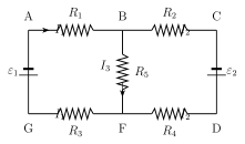
Drawn by us to help you understand the concept clearly, and verified to make sure it's accurate. For exams, practice from your textbook's own diagram.
What this figure shows. A multi-loop electrical network with (at least) six labelled nodes -- A, B, C, D, F and G -- connected by branches that between them carry resistors , , , and two cells of emf and , with branch currents , and marked with assumed directions on the relevant branches. Two closed loops are highlighted for the worked traversal in the text: loop A-B-F-G-A (traced clockwise, containing , , and the source , giving ) and loop B-F-D-C-B (traced anticlockwise, containing , , and the source ). The figure's purpose is to give a genuinely branching network (more than one independent loop) on which the systematic method of 9.2's numbered steps -- choose current directions, reduce variables via the junct …
Worked out. Two batteries, of emf 7 V (internal resistance 1 \Omega) and 13 V (internal resistance 2 \Omega), are connected in parallel with each other and with a 12 \Omega resistor, and the problem asks for the current through each battery branch and the potential difference across the 12 \Omega resistor. Applying Kirchhoff's voltage law to each battery's own loop through the 12 \Omega resistor gives two simultaneous equations in the two battery currents and ; solving them (equivalent to the parallel-cells/Millman result) gives A, A, a net external current A through the shared 12 \Omega resistor (the two battery currents partly oppose because the terminal voltage the parallel combination settles at, about 8.53 V, is closer to the smaller 7 V cell's emf, driving some current backwards through it) and hen …
Worked out. A network containing a 4 \Omega branch, a 3 \Omega branch and a 5 \Omega branch meeting at a junction F, driven by cells that are treated as having negligible internal resistance, asks for the currents through the 4 \Omega and 3 \Omega resistors. The book's own worked method is: write the junction-law equation at F ( for the three branch currents meeting there), then apply Kirchhoff's voltage law around two independent loops of the network to get two more simultaneous equations, and solve the resulting system for , and together. The exact resistor-to-node wiring in the original circuit diagram did not survive the text extraction cleanly enough to re-derive the intermediate loop equations independently with confidence, so the book's own final printed results are reported as-is: A, A (with the negative sign in the equations showing this current actually flows from F to C, opposite to the direction first assumed), and hence $I_3 = I_ …