Physics · Ch 9 — Current Electricity
Potentiometer Principle
Potentiometer Principle
A potentiometer consists physically of a long wire AB, of length L, resistance R and uniform cross-sectional area A, connected across a driving cell of emf and internal resistance r (together with a key and a rheostat, used to set a convenient current). When the circuit is switched on, a steady current
flows the length of the wire. The potential difference across the whole wire is then, by Ohm's law,
and dividing this by the wire's own length L gives the potential difference PER UNIT LENGTH of the wire,
As long as the driving emf (and hence the current I) stays constant, this quantity stays constant too. It is called the potential gradient of the wire, usually denoted K, and can be defined simply as the potential difference per unit length of the potentiometer wire.
Because K is constant along a uniform wire carrying a steady current, the potential difference between the starting point A and ANY other point on the wire is directly proportional to the length of wire in between. If C is a point on the wire at a distance from A, then
…
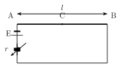
Drawn by us to help you understand the concept clearly, and verified to make sure it's accurate. For exams, practice from your textbook's own diagram.
What this figure shows. A long, uniform potentiometer wire AB of length L, resistance R and cross-sectional area A, connected in series with a driving cell of emf and internal resistance r (and, in practice, a key and rheostat not separately labelled here) so that a steady current I flows the length of the wire from A to B when the circuit is switched on. A point C is marked on the wire at a distance from end A, illustrating that the potential difference between A and this arbitrary point is what the potential-gradient relation (with constant along the uniform wire) is used to compute; no galvanometer, jockey or second (measured) cell appears in this figure, sin …