Physics · Ch 16 — Semiconductor Devices
The Common Emitter (CE) Characteristic
The Common Emitter (CE) Characteristic
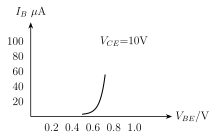
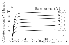
Using the circuit of Fig. 16.22, two standard characteristic curves are measured for a transistor in the common emitter configuration. The INPUT CHARACTERISTIC (Fig. 16.23) plots the base current against the base-emitter voltage , with the collector-emitter voltage held fixed throughout the measurement. As expected for what is, after all, a forward-biased p-n junction, the curve stays close to zero current until exceeds the junction's barrier potential, after which rises steeply, essentially reproducing the shape of an ordinary forward diode characteristic. From this curve, the INPUT DYNAMIC RESISTANCE is defined as -- the (small-signal) resistance the base-emitter junction presents to a changing input signal.\n\nThe OUTPUT CHARACTERISTIC (Fig. 16.24) plots the collector current against the collector-emitter voltage , this time with the base current held fixed for each individual curve -- different values of give a whole FAMILY of such curves, with larger producing correspondingly larger . Within each curve, rises very sharply for small near the origin, but then quickly flattens out into a nearly HORIZONTAL line for larger : as long as the collector-base junction stays reverse biased, is essentially INDEPENDENT of , and depends instead almost entirely on (via ). From this curve, the OUTPUT DYNAMIC RESISTANCE is defined as -- since the output curve is nearly flat, is small for a given , so works out to …
Drawn by us to help you understand the concept clearly, and verified to make sure it's accurate. For exams, practice from your textbook's own diagram.
What this figure shows. A graph with base current on the vertical axis and base-emitter voltage on the horizontal axis, plotted at one fixed (constant) value of . The curve starts essentially flat along the horizontal axis (negligible ) for small , until exceeds the barrier/knee potential, after which the curve bends upward and rises steeply with further increases in -- the same characteristic shape as an ordinary forward-biased p-n junction diode, since the base-emitter junction IS a forward-biased diode. The input dynamic resistance is read off as the (reciprocal) slope …
Drawn by us to help you understand the concept clearly, and verified to make sure it's accurate. For exams, practice from your textbook's own diagram.
What this figure shows. A graph with collector current on the vertical axis and collector-emitter voltage on the horizontal axis, drawn as a FAMILY of several curves, each corresponding to a different fixed (constant) value of base current -- curves for larger sit HIGHER on the graph (larger ) than curves for smaller , since a larger base current produces a proportionally larger collector current. Within any single curve (fixed ), the collector current rises very steeply for small near the origin, then bends and becomes essentially FLAT/HORIZONTAL for larger -- i.e. stays almost constant, independent of further increases in , as long as the collector-base junction remains reverse biased. The output dynamic resistance (at constant ) is read off as the (large, s …