Physics · Ch 16 — Semiconductor Devices
Logic Gates
Logic Gates
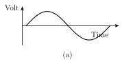
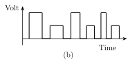
So far, the signals discussed in this course -- and in the previous class -- have been continuously varying (ANALOG) signals: a sinusoidal voltage, for instance, smoothly takes on every intermediate value between its minimum and maximum as time passes (Fig. 16.26a). A DIGITAL signal, by contrast, can take on only TWO discrete values (states) at any instant -- typically a LOW voltage (around 0 V) or a HIGH voltage (around +5 V) -- switching abruptly between them rather than passing smoothly through intermediate values; a square wave is the standard example (Fig. 16.26b). An electronic circuit that processes only digital signals is called a DIGITAL CIRCUIT, and the branch of electronics dealing with such circuits is DIGITAL ELECTRONICS.\n\nA LOGIC GATE is a digital circuit with one or more input signals but only ONE output signal, whose output follows some definite logical relationship to its inputs -- it is a switching circuit, and the name 'gate' reflects that it controls (gates) the flow of a signal or of information according to that logical rule. Like the inputs, a logic gate's output can only ever be in one of two states, high (1) or low (0), and which state it takes at any moment depends entirely on the combination of states present at its inputs. A gate's behaviour is completely and unambiguously captured by its TRUTH TABLE, which simply lists every possible combination of input states alongside the corresponding output for each -- and equally completely (and more compactly) by its BOOLEAN EXPRESSION, a short mathematical statement relating output to inputs using the …
Drawn by us to help you understand the concept clearly, and verified to make sure it's accurate. For exams, practice from your textbook's own diagram.
What this figure shows. A voltage-vs-time graph showing a smooth, continuously varying SINUSOIDAL waveform -- rising and falling gradually through every intermediate value between its minimum and maximum, with no discrete jumps or flat plateaus, illustrating that an analog signal can take on ANY value within its range at any instant, not just a fixed …
Drawn by us to help you understand the concept clearly, and verified to make sure it's accurate. For exams, practice from your textbook's own diagram.
What this figure shows. A voltage-vs-time graph showing a SQUARE wave: the voltage jumps abruptly (near-instantaneously) between exactly two fixed horizontal levels -- a LOW level (at or near 0 V) and a HIGH level (a fixed positive value such as +5 V) -- staying flat at one level for a stretch of time, then jumping vertically to the other level and staying flat there for another stretch, repeating periodically; illustrating that a digital signal only ever occupies one of two discrete stat …