Physics · Ch 5 — Electrostatic Potential and Capacitance
Capacitors in Parallel
Capacitors in Parallel
Concept: Why Parallel Connection Increases Capacitance
When capacitors are connected in parallel, the potential difference across each capacitor is the same (equal to the supply voltage ). However, the charge stored on each capacitor can be different, depending on its individual capacitance. The total charge stored by the combination is the sum of the charges on all capacitors. This makes the effective capacitance larger than any individual capacitor.
Derivation for Two Capacitors
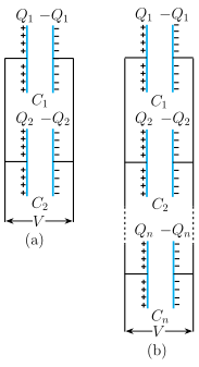
Consider two capacitors and connected in parallel across a voltage .
- Same voltage:
- Charge on each:
- Total charge stored by the combination:
- For an equivalent capacitor (one capacitor that stores the same total charge at the same voltage ), we have:
- Substituting the expressions for and :
- Cancelling (since ):
General Formula for Capacitors in Parallel
For capacitors connected in parallel:
- Total charge:
- Since each :
- Cancelling :
Result: The equivalent capacitance is simply the sum of the individual capacitances.
Key Points from the Example (NCERT Example 2.9)
The example shows a mixed network: three capacitors in series () connected in parallel with a fourth capacitor ().
- Step 1: Find effective capacitance of the series group ():
- Step 2: This is in parallel with : …
Drawn by us to help you understand the concept clearly, and verified to make sure it's accurate. For exams, practice from your textbook's own diagram.
The figure shows two schematic diagrams, (a) and (b), illustrating the parallel combination of capacitors.
In panel (a), two parallel-plate capacitors, labelled C₁ and C₂, are drawn one above the other. Each capacitor consists of a pair of vertical plates: the left plate is marked with a '+' sign and the right plate with a '−' sign. The left plates of both capacitors are connected by a common vertical rail, and the right plates are similarly connected by another common vertical rail. A horizontal double-headed arrow labelled V spans the two rails at the bottom, indicating that the same potential difference is applied across both capacitors. The charge on each capacitor is explicitly shown: C₁ carries charges on its left plate and on its right plate; C₂ carries and respectively.
Panel (b) extends this idea to capacitors. The capacitors C₁, C₂, ..., Cₙ are stacked vertically, all sharing the same left and right vertical rails. A dotted vertical stretch between C₂ and Cₙ indicates that any number of intermediate capacitors can be omitted for generality. Each capacitor is labelled with its charge: for C₁, for C₂, ..., for Cₙ. The same bottom arrow V again shows that the potential difference across every capacitor is identical.
Physical idea: In a parallel combination, all capacitors experience the same voltage . The total charge stored in the combination is the sum of the charges on each capacitor. Because for each, the total charge is . This leads to the effective (equivalent) capacitance being the sum of the individual capacitances.
Key formulas developed from this figure:
For two capacitors in parallel:
Total charge:
Effective capacitance satisfies , so:
…