Q.Three capacitors each of capacitance 9 pF are connected in series.
🔒You're viewing a preview — the full solution, concept, methods & PYQ mapping are locked.
🔒 Start your 14-day free trial to unlock the full solution →Concept understanding — Capacitor Network Analysis
Capacitor Network Analysis
Imagine you have a bucket of water and a pipe. The bigger the bucket, the more water it can hold for a given water pressure. A capacitor does the same thing with electric charge — it stores charge when a voltage is applied. The "size" of the bucket is called capacitance (C), measured in farads (F).
Now, what happens when you connect several buckets together with pipes? That's a capacitor network. The analysis is about finding one equivalent bucket (a single capacitor) that behaves exactly like the whole network.
The Core Idea: Charge and Voltage Must Match
When you connect capacitors, two things are always true:
- Charge conservation: Total charge in a closed part of the circuit stays the same unless a battery pushes more in.
- Voltage is shared: The voltage across each capacitor depends on how they're wired.
There are only two basic ways to connect them. Everything else is a combination of these two.
Series Connection: One Path, Shared Charge
Connect capacitors end-to-end, like train cars. The same current flows through each, so each capacitor stores the same amount of charge Q.
But the total voltage across the combination is the sum of the individual voltages:
Vtotal=V1+V2+V3+…
Since V=Q/C for each capacitor, we get:
CeqQ=C1Q+C2Q+C3Q+…
Cancel Q (it's the same everywhere):
Ceq1=C11+C21+C31+…
Intuition: Adding capacitors in series makes the equivalent capacitance smaller than the smallest individual one. Why? Because you're effectively making the "bucket" longer and narrower — harder to fill.
A common mistake: students treat series capacitors like series resistors (adding reciprocals for resistors, but adding directly for capacitors). It's the opposite. For resistors in series: Req=R1+R2. For capacitors in series: 1/Ceq=1/C1+1/C2.
Parallel Connection: Multiple Paths, Same Voltage
Connect capacitors side by side, like buckets with their bottoms connected by a wide pipe. Each capacitor sees the same voltage V across it.
But the total charge stored is the sum of charges on each:
Qtotal=Q1+Q2+Q3+…
Since Q=CV for each:
CeqV=C1V+C2V+C3V+…
Cancel V:
Ceq=C1+C2+C3+…
Intuition: Adding capacitors in parallel makes the equivalent capacitance larger — you're just adding more bucket area. Easy to fill.
| Connection | Equivalent Formula | What happens to Ceq |
|------------|-------------------|----------------------------------|
| Series | 1/Ceq=∑1/Ci | Gets smaller than smallest |
| Parallel | Ceq=∑Ci | Gets larger than largest |
How to Analyze Any Network
- Spot the pattern: Look for capacitors that are clearly in series (only two terminals, no branching between them) or clearly in parallel (both ends connected together).
- Replace step by step: Replace each simple series or parallel group with its equivalent capacitor. Redraw the circuit after each step.
- Repeat until you have one capacitor.
This is exactly like simplifying resistor networks — but with the reciprocal formula for series. If you can do resistor networks, you can do capacitor networks. Just flip the series formula.
A Worked Example
Suppose you have three capacitors: C1=2 μF, C2=3 μF, C3=6 μF. C2 and C3 are in parallel, and that combination is in series with C1. …
Concept: Capacitor Network Analysis — For capacitors in series, the reciprocal of the total capacitance is the sum of the reciprocals of individual capacitances, and the charge on each capacitor is the same.
Step 1: Total capacitance in series
For three identical capacitors C=9 pF in series:
Ctotal1=C1+C1+C1=C3
So
Ctotal=3C=39 pF=3 pF
Step 2: Charge on the combination
When connected to a 120 V supply, the charge on each capacitor (same for all in series) is:
Q=Ctotal×V=3 pF×120 V=360 pC
Step 3: Potential difference across each capacitor …
For identical capacitors in series, the total capacitance is the individual value divided by the number of capacitors — here 3 pF. Since they are identical, the supply voltage divides equally across each, giving 40 V per capacitor.
When capacitors are connected in series, the charge on each capacitor is the same, but the voltage across the combination splits across them. This is the mirror image of resistors in parallel — and it’s a common source of confusion.
The key idea: for n identical capacitors in series, the total capacitance is simply C/n, and the voltage across each is V/n. Let’s see why.
1. Total capacitance in series
For capacitors in series, the reciprocal of the total capacitance is the sum of the reciprocals of the individual capacitances:
Ctotal1=C11+C21+C31
Here each C=9 pF, so:
Ctotal1=91+91+91=93=31
Therefore:
Ctotal=3 pF
For n identical capacitors each of capacitance C in series, the shortcut is Ctotal=C/n. Here 9/3=3 pF — no need to write reciprocals each time.
2. Voltage across each capacitor
When the series combination is connected to a 120 V supply, the same charge Q appears on each capacitor. The voltage across a capacitor is V=Q/C.
Since the capacitors are identical, the charge Q is the same for all, and so the voltage across each is also the same. The total voltage is the sum of the individual voltages:
V1+V2+V3=120 V
If each voltage is V, then 3V=120 V, so:
V=40 V …
Method: Solving a Series Capacitor Network
This method finds the equivalent capacitance and the voltage split for capacitors connected end-to-end (series).
Steps
Step 1: Recognise the series connection and its defining property
In series there is only one conduction path, so the same charge Q sits on every capacitor (charge leaving one plate must reappear on the next). The supply voltage instead splits across the capacitors.
Step 2: Combine using the reciprocal rule
Ceq1=C11+C21+C31+… …
Showing the 12 most recent of 19 on this concept.
- TG EAPCET 2026Set eng-2026-05-09-FN1 markMCQQ.A, B and C are three parallel plate capacitors. If A and B are connected in series the effective capacitance is 6μF, if B and C are connected in series the effective capacitance is 4μF and, if A and C are connected in series the effective capacitance is 3μF. If these three capacitors are connected in parallel, the effective capacitance of the combination is (A) 26μF (B) 36.8μF (C) 13μF (D) 32.4μF
›Reveal solutionSolution
The problem gives three series-pair capacitances, which we invert to get sums of reciprocals; solving those three linear equations yields the individual capacitances, whose sum is the parallel capacitance — 13 μF.
We are told that for three capacitors A,B,C (each with capacitance a,b,c in μF), the series combinations give:
a1+b1=61,b1+c1=41,a1+c1=31.
We want a+b+c, the parallel capacitance.
Why this works:
Series capacitance is the reciprocal of the sum of reciprocals. So each given series value is the reciprocal of a sum of two reciprocals. That gives us three linear equations in the three unknowns x=1/a, y=1/b, z=1/c. Solve for x,y,z, then invert to get a,b,c, and add.
- Set up the reciprocals. Let x=a1,y=b1,z=c1. Then:
x+y=61,y+z=41,x+z=31.
- Solve the linear system. Add all three equations:
(x+y)+(y+z)+(x+z)=61+41+31.
Left side: 2(x+y+z). Right side: common denominator 12 gives 122+3+4=129=43.
So:
2(x+y+z)=43⇒x+y+z=83.
- Find each reciprocal individually. Subtract x+y=61 from x+y+z=83:
z=83−61=249−244=245.
Subtract y+z=41 from x+y+z=83:
x=83−41=83−82=81.
Subtract x+z=31 from x+y+z=83: …
- TG EAPCET 2026Set eng-2026-05-10-FN1 markMCQQ.The ratio of the energies stored in capacitors A, B and C when connected in parallel to a dc supply is 1:2:3. When they are connected in series to the same dc supply, if the energy stored in capacitor C is 75 mJ, then the energy stored in capacitor A is (A) 150 mJ (B) 25 mJ (C) 225 mJ (D) 75 mJ
›Reveal solutionSolution
The parallel-energy ratio fixes CA:CB:CC=1:2:3; in series every capacitor carries the same charge, so energy ∝1/C, giving EA=3EC=225mJ.
Step 1 — Find the capacitances (parallel case).
In parallel all capacitors share the same voltage V, and E=21CV2, so energy ∝C. Since EA:EB:EC=1:2:3,
CA:CB:CC=1:2:3⇒CA=C,CB=2C,CC=3C.
Step 2 — Series case.
In series every capacitor carries the same charge Q, and E=2CQ2, so energy ∝C1: …
- TG EAPCET 2025Set eng-2025-05-03-AN1 markMCQQ.A parallel plate capacitor with air as dielectric has a capacitance of 4 μF. The space between the plates of the capacitor is completely filled with a material of dielectric constant 5 and charged to a potential of 100 V. The work done to completely remove the dielectric material after the capacitor is disconnected from the battery is (A) 0.1 J (B) 0.5 J (C) 0.6 J (D) 0.4 J
›Reveal solutionSolution
The capacitor is disconnected, so the charge Q stays fixed while the dielectric is removed. The work done equals the increase in stored energy, Uf−Ui=0.5−0.1=0.4 J, option (D).
Concept & intuition
Once disconnected from the battery, the charge on the plates is trapped, so Q is constant. Removing the dielectric lowers the capacitance (C=κC0), which raises the voltage. The work you do pulling the slab out goes entirely into the extra stored electrostatic energy.
- Capacitance with dielectric
Ci=κC0=5×4 μF=20 μF.
- Charge (constant after disconnection) — charged to 100 V with the dielectric in place:
Q=CiV=20×10−6×100=2×10⁻³ C.
- Capacitance after removing the dielectric
Cf=C0=4 μF.
- Final voltage (Q fixed):
Vf=CfQ=4×10−62×10−3=500 V.
- Stored energies
Ui=21CiV2=21(20×10−6)(100)2=0.1 J,
Uf=21CfVf2=21(4×10⁻⁶)(500)2=0.5 J.
- Work done = increase in energy
- TG EAPCET 2025Set eng-2025-05-03-AN1 markMCQQ.A capacitor and a resistor of resistance 1003 Ω are connected in series to an ac source of voltage 100sin(200t) V, where ‘t’ is time in second. If the phase difference between the voltage and the current in the circuit is 30∘, then the capacitance of the capacitor is (A) 30 μF (B) 50 μF (C) 100 μF (D) 150 μF
›Reveal solutionSolution
In an RC series circuit, the phase angle ϕ satisfies tanϕ=ωCR1. Given ϕ=30∘, ω=200 rad/s, and R=1003 Ω, solving gives C=50 μF, so option (B) is correct.
Concept & Intuition
In a series RC circuit driven by an AC source, the resistor’s voltage is in phase with the current, while the capacitor’s voltage lags the current by 90∘. The total voltage is the phasor sum of these two, so the current leads the voltage by some angle ϕ between 0∘ and 90∘. That phase difference is given by tanϕ=RXC, where XC=ωC1 is the capacitive reactance. Here we know ϕ and R, so we can solve for C.
Step-by-step solution
-
Identify given quantities
- Resistance: R=1003 Ω
- Source voltage: V(t)=100sin(200t) V, so angular frequency ω=200 rad/s
- Phase difference: ϕ=30∘ (current leads voltage in an RC circuit)
-
Write the phase relation for an RC series circuit
For a series RC circuit, the impedance phasor diagram gives:
tanϕ=RXC
where XC=ωC1 is the capacitive reactance.
(Note: Some textbooks define ϕ as the angle by which voltage leads current; here current leads voltage, so ϕ is positive and the formula still holds with XC in the numerator.)
- Substitute known values
tan30∘=ωCR1
Since tan30∘=31, we have:
31=ωCR1
- Solve for C Invert both sides:
3=ωCR
So:
C=ωR3 …
-
- TG EAPCET 2025Set eng-2025-05-03-FN1 markMCQQ.A parallel plate capacitor with air as dielectric has a capacitance of 4μF. The space between the plates of the capacitor is completely filled with a material of dielectric constant 5 and charged to a potential of 100V. The work done to completely remove the dielectric material after the capacitor is disconnected from the battery is (A) 0.4J (B) 0.5J (C) 0.1J (D) 0.6J
›Reveal solutionSolution
After the battery is disconnected the charge is fixed. Work done = final energy − initial energy =0.5−0.1=0.4J, option (A).
Air-filled capacitance is C0=4μF. With the dielectric (κ=5) in place,
C=κC0=5×4=20μF.
It is charged to V=100V, so the stored charge is
Q=CV=20×10−6×100=2×10⁻³C.
The battery is then disconnected, so Q stays constant while the dielectric is removed. Using U=2CQ2:
Initial energy (dielectric in, C=20μF):
Ui=2×20×10−6(2×10⁻³)2=40×10−64×10−6=0.1J. …
- TG EAPCET 2025Set eng-2025-05-03-FN1 markMCQQ.A capacitor and a resistor of resistance 1003 Ω are connected in series to an ac source of voltage 100sin(200t) V, where ‘t’ is time in second. If the phase difference between the voltage and the current in the circuit is 30∘, then the capacitance of the capacitor is (A) 50 μF (B) 30 μF (C) 150 μF (D) 100 μF
›Reveal solutionSolution
In an RC series circuit, the phase angle ϕ satisfies tanϕ=ωCR1. Given ϕ=30∘, R=1003 Ω, and ω=200 rad/s, solving gives C=50 μF, so the correct option is (A).
Concept & Intuition
When a resistor and capacitor are in series with an AC source, the voltage across the resistor is in phase with the current, but the voltage across the capacitor lags the current by 90∘. The total voltage from the source is the phasor sum of these two voltages. The phase difference ϕ between the source voltage and the current is determined by the ratio of capacitive reactance XC=ωC1 to resistance R:
tanϕ=RXC=ωCR1.
Here ϕ=30∘ is given, so we can directly solve for C.
Step-by-step solution
-
Identify given quantities
- Resistance: R=1003 Ω
- Source voltage: V(t)=100sin(200t) V This tells us the angular frequency ω=200 rad/s.
- Phase difference: ϕ=30∘ (voltage leads current in an RC circuit? Actually, in a series RC circuit, current leads voltage, so ϕ is usually taken as the angle by which voltage lags current. But the problem says "phase difference between the voltage and the current" — we take its magnitude as 30∘.)
-
Write the phase relation
For a series RC circuit, the impedance phase angle ϕ satisfies:
tanϕ=RXC=ωCR1.
Here ϕ=30∘, so tan30∘=31.
- Set up the equation
ωCR1=31.
Substitute ω=200 and R=1003: …
-
- TG EAPCET 2025Set ap-2025-04-29-AN1 markMCQQ.Two resistors of resistances 4 Ω and 8 Ω are connected in parallel in the left gap of the meter bridge and two resistors of resistances 8 Ω and 4 Ω are connected in series in the right gap of the meter bridge. The balancing length from the left end of the bridge wire is (A) 11100 cm (B) 9200 cm (C) 11180 cm (D) 11200 cm
›Reveal solutionSolution
The meter bridge balances when the ratio of the left-gap equivalent resistance to the right-gap equivalent resistance equals the ratio of the corresponding wire lengths. The left gap has 4 Ω and 8 Ω in parallel, giving 38 Ω; the right gap has 8 Ω and 4 Ω in series, giving 12 Ω. Solving the bridge equation yields a balancing length of 11200 cm from the left end.
The meter bridge works on the same principle as the Wheatstone bridge: at balance, the ratio of the two resistances in one pair equals the ratio of the two resistances in the other pair. Here, the left gap holds a combination of two resistors, and the right gap holds another combination. The wire of length 100 cm acts as the two ratio arms — the portion from the left end to the sliding contact has resistance proportional to its length l, and the remaining portion has resistance proportional to 100−l.
So the key is to find the equivalent resistance in each gap first, then apply the bridge condition.
- Left gap — parallel combination Two resistors 4 Ω and 8 Ω are in parallel. The equivalent resistance RL is given by
RL1=41+81=82+81=83
so
RL=38 Ω.
- Right gap — series combination Two resistors 8 Ω and 4 Ω are in series. The equivalent resistance RR is simply
RR=8+4=12 Ω.
- Bridge balance condition In a meter bridge, if the balancing length from the left end is l cm, then
RRRL=100−ll.
Substitute the values:
128/3=100−ll.
- Simplify the left-hand side
128/3=38×121=368=92.
So the equation becomes
92=100−ll.
- Solve for l Cross-multiply:
2(100−l)=9l⇒200−2l=9l.
Bring terms together:
- TG EAPCET 2025Set ap-2025-04-29-FN1 markMCQQ.The potential difference between the plates of a parallel plate capacitor is changing at the rate of 3.5×10⁶ Vs−1. If the displacement current is 7 A, the capacitance of the capacitor is (A) 8 μF (B) 2 μF (C) 4 μF (D) 6 μF
›Reveal solutionSolution
Displacement current equals conduction current in the capacitor circuit, so Id=CdtdV. Using the given values, C=2 μF.
The key idea here is that displacement current is not some separate, mysterious quantity — it is the current that "flows" through the gap between the capacitor plates when the electric field changes. In a circuit containing a capacitor, the displacement current between the plates is exactly equal to the conduction current in the wires. That means we can treat the displacement current just like the ordinary current charging the capacitor.
For a capacitor, the charge on the plates is Q=CV, and the current is the rate of change of charge: I=dtdQ=CdtdV. Since the displacement current Id equals this charging current, we have a direct relation.
- Write the relation between displacement current and the rate of change of potential difference:
Id=CdtdV
- Substitute the given values:
7 A=C×(3.5×10⁶ V/s)
- Solve for C: …
- TG EAPCET 2024Set eng-2024-05-10-AN1 markMCQQ.Two capacitors of capacitances 1μF and 2μF can separately withstand potentials of 6kV and 4kV respectively. The total potential, they together can withstand when they are connected in series is (A) 9kV (B) 4kV (C) 6kV (D) 2kV
›Reveal solutionSolution
In series the two capacitors share the same charge; the safe charge is set by the capacitor that hits its rating first. Here that safe charge gives 6kV+3kV=9kV — option (A).
Concept. Capacitors in series carry the same charge Q. Each has a maximum charge it can hold before its rated voltage is exceeded, Qmax=CVrated. The combination is safe only up to the smaller of the two maximum charges.
Maximum charge of each capacitor.
Q1=C1V1=(1μF)(6kV)=6mC,Q2=C2V2=(2μF)(4kV)=8mC.
Limiting charge. The safe common charge is the smaller value, Q=6mC (pushing to 8mC would put 8kV across the 1μF capacitor, exceeding its 6kV rating).
Voltages at this charge. …
- TG EAPCET 2024Set eng-2024-05-10-AN1 markMCQQ.When two identical resistors are connected in series to an ideal cell, the current through each resistor is 2A. If the resistors are connected in parallel to the cell, the current through each resistor is (A) 4A (B) 2A (C) 8A (D) 1A
›Reveal solutionSolution
The key idea is that the cell voltage is fixed, so the current through each resistor in parallel is determined by the same voltage across each resistor. From the series case we find the cell voltage, then apply it to the parallel case. The current through each resistor in parallel is 4A, so the correct option is (A).
Concept and intuition:
When resistors are identical, their resistance R is the same. In series, the total resistance is 2R, so the cell’s voltage V is Iseries×2R=2×2R=4R. In parallel, each resistor gets the full cell voltage V, so the current through each is V/R=4R/R=4A. The trick is to realize the cell is ideal (constant voltage), so the parallel current is simply double the series current through one resistor.
- Find the resistance of each resistor from the series case. In series, total resistance Rseries=R+R=2R. The current is 2A, so by Ohm’s law:
V=Iseries⋅Rseries=2⋅2R=4R.
This tells us the cell voltage in terms of R.
- Now consider the parallel connection. In parallel, each resistor is directly across the cell, so the voltage across each is V. The current through one resistor is:
Iparallel=RV=R4R=4A.
- Check the total current (optional but insightful). …
- TG EAPCET 2024Set eng-2024-05-11-FN1 markMCQQ.A capacitor of capacitance ‘C’ is charged to a potential ‘V’ and disconnected from the battery. Now if the space between the plates is completely filled with a substance of dielectric constant ‘K’, the final charge and the final potential on the capacitor are respectively (A) KCV and KV (B) CV and KV (C) KCV and KV (D) KCV and KV
›Reveal solutionSolution
When a charged capacitor is isolated from the battery and then a dielectric is inserted, the charge remains constant (no path to change it), while the capacitance increases by a factor K, so the voltage drops by the same factor. The final charge is CV and the final potential is V/K, which corresponds to option (B).
Concept and Intuition
The key idea is that the capacitor is disconnected from the battery before the dielectric is inserted. That means there is no external circuit to supply or remove charge. The charge on the plates is therefore fixed — it cannot change. The dielectric, however, changes the capacitance: inserting a material of dielectric constant K multiplies the original capacitance by K. Since Q=CV must hold at every moment, if C increases and Q stays the same, the voltage V must decrease proportionally. This is exactly the opposite of what happens if the battery stays connected (where voltage is fixed and charge increases). The common mistake is to confuse these two scenarios.
Step-by-step reasoning
- Initial state The capacitor has capacitance C and is charged to potential V while connected to a battery. The charge stored is
Q0=CV.
Then the battery is disconnected. At this moment, the charge on the plates is Q0 and there is no path for it to change.
- Inserting the dielectric When the space between the plates is completely filled with a substance of dielectric constant K, the capacitance becomes
C′=KC.
This is a fundamental property: a dielectric reduces the electric field for the same charge, allowing more charge to be stored per volt, hence capacitance increases by factor K.
- Charge remains constant Because the capacitor is isolated (no battery, no conducting path), the charge cannot leave or arrive. Therefore the final charge is exactly the same as the initial charge:
Qfinal=Q0=CV.
- Finding the final potential The fundamental relation for a capacitor is Q=CV. Using the new capacitance and the unchanged charge:
- TG EAPCET 2023Set eng-2023-05-13-FN1 markMCQQ.The effective capacitance between points A and B shown in the figure is [FIGURE] (A) 10 μF (B) 15 μF (C) 20 μF (D) 25 μF
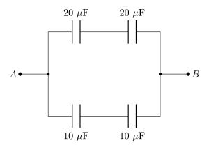
›Reveal solutionSolution
To find the effective capacitance between points A and B, we analyze the arrangement of capacitors and apply the rules for capacitors in series and parallel.
The effective capacitance is 15 μF.
To solve for the effective capacitance between points A and B, we first need to understand how capacitors combine in series and parallel configurations. The intuition behind this is based on how charge and voltage distribute across capacitors:
- Capacitors in Series: When capacitors are connected in series, the total capacitance Ctotal can be calculated using the formula:
Ctotal1=C11+C21+…+Cn1
This is because the same charge Q flows through each capacitor, and the total voltage V across the series is the sum of the voltages across each capacitor.
- Capacitors in Parallel: When capacitors are connected in parallel, the total capacitance is simply the sum of the individual capacitances:
Ctotal=C1+C2+…+Cn
In this case, each capacitor experiences the same voltage V, and the total charge is the sum of the charges on each capacitor.
Now, let's apply these principles step by step to find the effective capacitance between points A and B.
Step-by-Step Calculation
-
Identify the Configuration: Examine the arrangement of the capacitors between points A and B. Assume we have two capacitors C1 and C2 in series, and a third capacitor C3 in parallel with the series combination.
-
Calculate Series Capacitance: If C1 and C2 are in series, we first calculate their combined capacitance Cs:
Cs1=C11+C21
Suppose C1=10 μF and C2=15 μF:
Cs1=101+151=303+302=305⟹Cs=530=6 μF …
🎓Unlock everything free for 14 days
- ✓Full step-by-step solutions
- ✓Concept-first explanations
- ✓Methods, shortcuts & mistakes
- ✓PYQ mapping + timed mock tests
Full access for 14 days. No credit card required.