Common Emitter Configuration – First Principles
Imagine you have a water tap. A small turn of the handle produces a large flow of water. That's amplification — a small input controlling a large output. The common emitter configuration is the transistor's version of that tap, and it's the most widely used amplifier arrangement in electronics.
The Intuition: Why "Common Emitter"?
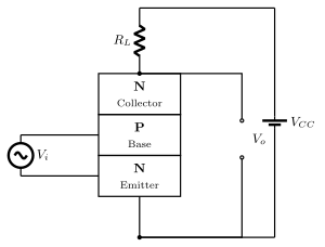
In any transistor circuit, one terminal must be shared between the input and the output. In the common emitter configuration, that shared terminal is the emitter. The input signal goes between base and emitter. The output is taken between collector and emitter. The emitter is common to both — hence the name.
Think of the emitter as the ground reference for the entire circuit. The base is the control terminal (the tap handle), and the collector is where the amplified output appears.
The Precise Statement
In a common emitter configuration:
- Input: between base and emitter
- Output: between collector and emitter
- Emitter: common to both input and output circuits
The transistor is biased so that the base-emitter junction is forward-biased (like a diode conducting) and the collector-base junction is reverse-biased. This is the normal active region of operation.
What Makes It Special: Both Current and Voltage Gain
Here's the key insight that makes this configuration so powerful. A small change in base current (ΔIB) causes a much larger change in collector current (ΔIC). The ratio is the transistor's current gain:
β=ΔIBΔIC
Typical values of β range from 50 to 300. So a tiny signal current at the base produces a large current at the collector.
But that's not all. The output is taken across a load resistor RC connected to the collector. The changing collector current flows through RC, producing a voltage change:
ΔVout=ΔIC×RC
Meanwhile, the input voltage change is just the small base-emitter voltage change (about 0.6 V for silicon, and the signal variation is only millivolts). The result is that the output voltage swing is much larger than the input voltage swing — you get voltage gain as well.
AV=ΔVinΔVout=−rbeβRC
where rbe is the small-signal base-emitter resistance (typically a few kilo-ohms).
The negative sign means the output is inverted — when the input goes up, the output goes down. This 180-degree phase shift is a hallmark of the common emitter amplifier.
The Trade-Off …