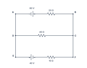
Q.Using Kirchhoff's rules, calculate the current through the 40Ω and 20Ω resistors in the following circuit:
🔒You're viewing a preview — the full solution, concept, methods & PYQ mapping are locked.
🔒 Start your 14-day free trial to unlock the full solution →Part (a)Concept understanding — Power Dissipation in Resistors
Power Dissipation in Resistors
Whenever charge is driven through a resistor, electrical energy is converted into heat. The rate of this conversion is the power dissipated.
Why a Resistor Heats Up
Inside a resistor, drifting electrons repeatedly collide with the vibrating lattice ions. Each collision transfers kinetic energy to the lattice, raising its temperature. The source (battery or AC supply) continually does work to keep the current flowing, and that work reappears as heat. This is Joule heating.
The Power Formulas (DC)
The power delivered to any device carrying current I across a potential difference V is
P=VI
For an ohmic resistor V=IR, so this can be written in three equivalent forms:
P=VI=I2R=RV2
The SI unit is the watt (W), where 1 W=1 J s−1.
Which form to use depends on what is fixed:
- Series elements share the same current, so P=I2R shows the larger resistor dissipates more.
- Parallel elements share the same voltage, so P=V2/R shows the smaller resistor dissipates more.
The total heat produced in time t is Q=Pt=I2Rt — Joule's law of heating.
Power Dissipation with AC
With alternating current the instantaneous power p(t)=i2(t)R fluctuates, but a resistor still only dissipates energy (it never returns any). The average power over a cycle is written with root-mean-square values:
Pavg=Irms2R=RVrms2=VrmsIrms
where for a sinusoid Irms=Im/2 and Vrms=Vm/2. This is precisely why rms values are defined: an AC of rms value Irms heats a resistor at the same average rate as a steady DC of value Irms.
A pure resistor has power factor 1 — voltage and current are in phase, so all the power supplied is dissipated. In inductors and capacitors, by contrast, the average dissipated power is zero; energy is only stored and returned.
Worked Example
A 100 Ω resistor carries a current of 0.5 A. …
Why this formula?
Power Dissipation in Resistors — Why the Formula Holds
Let's build this from first principles. The goal is to understand why a resistor dissipates power as heat, and how the formula P=I2R (and its equivalents) arise naturally.
1. What is "Power" in an Electrical Circuit?
Power is the rate of energy transfer — how much energy is converted from one form to another per unit time.
- In a resistor, electrical energy is converted into heat (thermal energy).
- The fundamental definition of electrical power is:
P=V⋅I
where:
- P = power (watts, W)
- V = voltage across the component (volts, V)
- I = current through the component (amperes, A)
Why this definition?
Voltage is energy per unit charge (V=qW), and current is charge per unit time (I=tq). Multiplying them gives energy per unit time — exactly power.
2. How Does a Resistor Behave? — Ohm's Law
A resistor obeys Ohm's Law:
V=I⋅R
where R is resistance (ohms, Ω). This is an empirical law — it describes how real resistors behave: the voltage across them is proportional to the current through them.
3. Deriving the Power Dissipation Formulas
We start with P=VI and substitute Ohm's Law in two ways.
Case A: Express power in terms of I and R
Replace V with IR:
P=(IR)⋅I=I2R
Interpretation:
- For a fixed resistance, power grows with the square of current.
- Doubling current quadruples the heat generated — this is why high currents cause wires to overheat.
Case B: Express power in terms of V and R
Replace I with RV:
P=V⋅(RV)=RV2
Interpretation:
- For a fixed voltage, power is inversely proportional to resistance.
- A low-resistance resistor (like a short circuit) dissipates huge power at a given voltage — that's why short circuits are dangerous.
4. The Physical "Why" — Energy Conversion at the Atomic Level
Why does this energy turn into heat?
- Electrons moving through a resistor collide with the atoms of the material.
- Each collision transfers kinetic energy from the electron to the atom, making the atom vibrate more — i.e., heating up the resistor.
- The rate at which this energy is lost by the electrons (and gained by the lattice) is exactly P=I2R.
Key insight:
The I2 term appears because:
- More current = more electrons per second. …
Part (b)Concept understanding — Meter Bridge
The Intuition: Finding a Hidden Resistance
Imagine you have a box with two terminals sticking out. Inside is a resistor of unknown value — call it X. You want to find out how many ohms it is. You have a collection of known resistors, a battery, and a sensitive galvanometer. How do you measure X without cutting it open?
The trick is to compare X against a known resistance R in a clever circuit called a Wheatstone bridge. The idea is simple: if you arrange four resistors in a diamond shape and adjust one of them until the galvanometer shows zero current, the four resistances satisfy a neat proportion. At that "balance" condition, the ratio of two adjacent resistors equals the ratio of the other two. So if three are known, the fourth is found by cross-multiplication.
A meter bridge is just a practical, cheap way to build that Wheatstone bridge using a single metre-long wire as two of the four resistors.
The Setup
Take a uniform wire exactly 1 metre long, stretched taut on a wooden board with a metre scale beside it. The wire has a constant cross-section and uniform resistivity, so its resistance per unit length is constant. That means the resistance of any piece of the wire is directly proportional to its length.
Now connect the circuit:
- The unknown resistor X is connected in the left gap.
- A known resistor R (from a resistance box) is connected in the right gap.
- A battery is connected across the ends of the metre wire (points A and C).
- A galvanometer has one end connected to the junction between X and R (point B), and the other end to a sliding jockey that can touch any point on the metre wire.
The jockey is the key. By sliding it along the wire, you effectively choose two resistances from the wire itself: the length l from the left end to the jockey, and the remaining length (100−l) from the jockey to the right end.
Finding the Balance Point
Slide the jockey gently along the wire while watching the galvanometer. At most positions, the needle will deflect. But at one particular point — the balance point — the galvanometer shows zero deflection. That means no current flows through the galvanometer, and the bridge is balanced.
At balance, the Wheatstone bridge condition gives:
RX=resistance of right segment of wireresistance of left segment of wire
Since the wire is uniform, resistance is proportional to length. So:
RX=100−ll
where l is the length (in cm) from the left end to the balance point.
X=R⋅100−ll
That's it. Measure l from the metre scale, plug in the known R, and you get X.
Why This Works — The Physics
The wire is not a magic component. It's just a long resistor whose resistance you can tap at any point. By sliding the jockey, you are effectively turning the wire into two variable resistors that always add up to the total resistance of the whole wire. The ratio l/(100−l) can be any value from nearly 0 to nearly infinity, so you can always find a balance for any X by choosing an appropriate R.
The beauty is that you don't need to know the wire's resistivity or its exact total resistance — only the ratio of lengths matters. That cancels out all material properties.
A common mistake is to forget that l is measured from the same end every time. If you measure from the left end for one reading, always measure from the left end. Also, the wire must be truly uniform — any kink or damage changes its resistance per unit length and ruins the proportionality.
A Worked Example
Suppose you take a known resistance R=10 Ω. You slide the jockey and find the balance point at l=40 cm. Then:
X=10⋅100−4040=10⋅6040=10⋅32≈6.67 Ω …
Part (a)
The left ends A,D,E of the three branches are joined by a plain wire (one node), and so are the right ends B,C,F (another node) — so this is three branches in parallel: top (80V cell +20Ω, A→B, current I2), middle (40Ω only, D→C, current I1), bottom (40V cell +10Ω, E→F, current I3).
Loop A→B→C→D→A: crossing the 80V cell from − to + (rise) then the 20Ω resistor with I2 (drop), then back through the 40Ω against I1 (rise):
80−20I2+40I1=0⇒I2−2I1=4(1)
Junction at node A/D/E: I1+I2+I3=0.
Loop D→C→F→E→D: through the 40Ω with I1 (drop), back through the 10Ω against I3 (rise) and the 40V cell from − to + (rise):
−40I1+10I3+40=0⇒I3=4I1−4
Combined with the junction rule (I3=−I1−I2): 4I1−4=−I1−I2⇒5I1+I2=4(2) …
- Kirchhoff's rules on the actual circuit (three branches — 80V+20Ω, 40Ω alone, and 40V+10Ω — sharing the same two end-nodes) give zero current through the 40Ω resistor and 4A through the 20Ω resistor;
- end error is the mismatch between the wire ends and the scale zeros (removed by interchanging R and S and averaging), and the balance conditions give S=10Ω.
Part (a)
Reading the circuit. The left ends of all three branches (A, D, E) are joined by a single plain connecting wire, so they are all at the same potential — call this node P. Likewise the right ends (B, C, F) are joined into one node Q. So the circuit is three branches in parallel between P and Q:
- Top branch, A→B: an 80V cell (its − terminal toward A) in series with a 20Ω resistor. Let I2 be its current, taken A→B.
- Middle branch, D→C: just a 40Ω resistor. Let I1 be its current, taken D→C.
- Bottom branch, E→F: a 40V cell (its + terminal toward E) in series with a 10Ω resistor. Let I3 be its current, taken E→F.
Junction rule at node P. Since P only connects to these three branches, the currents leaving it must sum to zero:
I1+I2+I3=0(junction rule)
Loop rule, loop A→B→C→D→A. From A to B: cross the cell from − to + (a rise of 80V), then the 20Ω resistor in the direction of I2 (a drop of 20I2); B to C is plain wire (no change); C to D crosses the 40Ω resistor against the assumed direction of I1 (a rise of 40I1); D to A is plain wire. Setting the total change around the closed loop to zero:
80−20I2+40I1=0⟹I2−2I1=4(1)
Loop rule, loop D→C→F→E→D. From D to C: the 40Ω resistor in the direction of I1 (a drop of 40I1); C to F is plain wire; F to E crosses the 10Ω resistor against I3 (a rise of 10I3) then the cell from − to + (a rise of 40V); E to D is plain wire:
−40I1+10I3+40=0⟹I3=4I1−4
Substituting the junction rule (I3=−I1−I2):
4I1−4=−I1−I2⟹5I1+I2=4(2) …
- CBSE 2026Set 55/1/11 markMCQQ.Two heaters rated as (P1,V) and (P2,V) are connected in series across a dc source of 2V volt. The power consumed by the combination will be (A) (P1+P2) (B) 2P1+P2 (C) 2(P1+P2)P1P2 (D) 4(P1+P2)P1P2
›Reveal solutionSolution
Each heater's resistance is found from its rated power and voltage; in series across 2V, the total power dissipated is 4(P1+P2)P1P2.
Why this approach works
When a device is rated at (P,V), it means that at voltage V it consumes power P. This rating tells us the device's resistance through P=RV2, so R=PV2. Once we know the resistances, we can treat the heaters as ordinary resistors in a series circuit and calculate the actual power consumed at the new operating voltage.
The key insight: rated values describe behavior at a specific voltage, but resistance is an intrinsic property that doesn't change. We extract the resistance from the rating, then analyze the actual circuit.
Step-by-step solution
-
Find the resistance of each heater from its rating.
For heater 1 rated at (P1,V):
R1=P1V2
For heater 2 rated at (P2,V):
R2=P2V2
-
Calculate the total resistance in series.
When connected in series, resistances add:
Rtotal=R1+R2=P1V2+P2V2=V2(P11+P21)=V2⋅P1P2P1+P2
-
Apply the actual supply voltage.
The combination is connected across 2V. The power consumed by a resistor is:
P=RtotalVapplied2
Substituting:
P=V2⋅P1P2P1+P2(2V)2=V2⋅P1P2P1+P24V2
- Simplify the expression. …
-
- CBSE 2026Set 55/2/11 markMCQQ.Two statements are given – one labelled Assertion (A) and the other Reason (R). Select the correct answer from the codes below: (A) Both (A) and (R) are true and (R) is the correct explanation of (A). (B) Both (A) and (R) are true, but (R) is not the correct explanation of (A). (C) (A) is true, but (R) is false. (D) (A) is false and (R) is also false. Assertion (A) : Two electric heaters of power P1 and P2(>P1) are joined in series across a dc source of voltage V. The power consumed by the combination will be less than that consumed by P1 when connected across the same source. Reason (R) : The power consumed by an electric device when connected to a dc source of voltage V is proportional to its resistance.
›Reveal solutionSolution
The key idea is that in series, the combined resistance is larger than either heater's resistance, so the total power drawn from the source is smaller. The assertion is true; the reason is false because power is inversely proportional to resistance for a fixed voltage, not proportional.
Concept and intuition
When you connect a device to a fixed DC voltage source V, the power it consumes is given by P=V2/R. For a fixed voltage, power is inversely proportional to resistance — a higher resistance draws less current and therefore consumes less power. The reason statement gets this backwards.
Now, when two heaters are joined in series, their resistances add up. Since each heater's resistance is Ri=V2/Pi (from Pi=V2/Ri), the series combination has a total resistance Rseries=R1+R2, which is larger than either R1 or R2 alone. With a larger resistance, the power drawn from the same voltage source must be smaller than the power drawn by either individual heater. In particular, it will be less than P1 (the smaller power heater, which has the larger resistance). So the assertion is correct, but for a reason opposite to what is stated.
Step-by-step reasoning
- Express each heater's resistance in terms of its rated power. For a heater rated at power P when connected to voltage V, we have P=V2/R, so R=V2/P. Therefore:
R1=P1V2,R2=P2V2.
Since P2>P1, it follows that R2<R1 (higher power means lower resistance).
- Find the total resistance when they are in series.
Rseries=R1+R2=V2(P11+P21).
Clearly Rseries>R1 (and also >R2).
- Compute the power consumed by the series combination. Using P=V2/R again:
Pseries=RseriesV2=V2(P11+P21)V2=P11+P211=P1+P2P1P2.
- Compare Pseries with P1. Since P1>0, we have P1+P2>P2, so Pseries=P1+P2P1P2<P2P1P2=P1. …
- CBSE 2026Set ANNUAL1 markMCQQ.An unknown resistance R1 is connected in series with a resistance of 10 ohms. This combination is connected to one gap of a meter bridge, while a resistance R2 is connected in the other gap, the balance point is obtained at a distance of 50cm. When 10 ohms resistance is removed the balance point shifts to 40cm. The value of R1 is –(a) 10 ohms(b) 20 ohms(c) 40 ohms(d) 60 ohms
›Reveal solutionSolution
Two meter-bridge balance equations (with and without the extra 10Ω) solve for R1.
Meter bridge balance condition: QP=100−ll (ratio of the two gap resistances equals the ratio of the wire lengths).
With the 10Ω in series with R1, balance at 50 cm:
R2R1+10=5050=1⟹R2=R1+10
…
- CBSE 2025Set ANNUAL1 markMCQQ.If R1 and R2 are respectively the filament resistance of a 200 W bulb and a 100 W bulb designed to operate on the same voltage, then –(a) R1 = 2R2(b) R2 = 2R1(c) R2 = 4R1(d) R1 = 4R2
›Reveal solutionSolution
Since power P=V2/R at fixed voltage, the lower-power bulb has the higher filament resistance.
Both bulbs operate at the same voltage V. Using P=RV2, so R=PV2.
For the 200 W bulb: R1=200V2
For the 100 W bulb: R2=100V2=2002V2=2R1
…
- CBSE 2024Set ANNUAL1 markMCQQ.Energy dissipated in LCR circuit is in(a) L only(b) C only(c) R only(d) All of these
›Reveal solutionSolution
Over a full AC cycle, a pure inductor and a pure capacitor store and release energy with zero net dissipation; only the resistive element genuinely converts electrical energy to heat.
In an LCR series circuit driven by an AC source, the current and voltage across L and C are 90 degrees out of phase with each other, so the average power delivered to a pure inductor or a pure capacitor over one complete cycle is zero:
PL=PC=0(average, over one cycle)
…
- CBSE 2023Set 55/4/11 markMCQQ.Two statements are given — one labelled Assertion (A) and the other labelled Reason (R). Select the correct answer from the codes (A), (B), (C) and (D) as given below. (A) Both Assertion (A) and Reason (R) are true and Reason (R) is the correct explanation of the Assertion (A). (B) Both Assertion (A) and Reason (R) are true, but Reason (R) is not the correct explanation of the Assertion (A). (C) Assertion (A) is true, but Reason (R) is false. (D) Assertion (A) is false and Reason (R) is also false. Assertion (A) : When three electric bulbs of power 200 W, 100 W and 50 W are connected in series to a source, the power consumed by the 50 W bulb is maximum. Reason (R) : In a series circuit, current is the same through each bulb, but the potential difference across each bulb is different.
›Reveal solutionSolution
In a series circuit, the bulb with the lowest rated power has the highest resistance, and since power dissipated in series is P=I2R, the 50 W bulb consumes the most power. The reason correctly states that current is same but voltage differs, but it does not explain why the 50 W bulb gets maximum power — that requires linking resistance to rated power. So both statements are true, but Reason is not the correct explanation.
The Concept — Why This Works
The trap here is intuitive: we usually think a 200 W bulb is "more powerful." But that's when each bulb is connected individually to the same voltage (say 220 V). In that case, a higher wattage means it draws more current and glows brighter.
In series, the situation flips. The key idea:
- Each bulb is designed for a fixed voltage (the mains voltage). Its resistance is fixed by R=V2/Prated.
- A lower rated power means a higher resistance (since P is in the denominator).
- In series, current I is the same through all bulbs. Power dissipated in a bulb is Pactual=I2R.
- So the bulb with the largest resistance (the 50 W bulb) dissipates the most power in series.
That's the core physics. Now let's check the statements carefully.
Step-by-Step Verification
1. Find the resistances of the bulbs.
Assume each bulb is rated for the same voltage V (typically 220 V in household circuits, but the exact value doesn't matter — it cancels out).
Using P=V2/R, we get R=V2/P.
- For 200 W bulb: R200=V2/200
- For 100 W bulb: R100=V2/100
- For 50 W bulb: R50=V2/50
Clearly, R50>R100>R200.
2. Connect them in series to the same source voltage V.
Total resistance: Rtotal=R200+R100+R50.
Current in the circuit:
I=RtotalV
This current is the same through each bulb (series property).
3. Power consumed by each bulb in series.
For any bulb: Pactual=I2R.
Since I is common, the bulb with the largest R gets the largest Pactual.
That's the 50 W bulb. So Assertion (A) is true.
4. Check Reason (R).
Reason says: "In a series circuit, current is the same through each bulb, but the potential difference across each bulb is different."
This is a true statement about series circuits. …
- CBSE 2022Set HE2171 markQ.Fill in the blank: Meter bridge is based on the principle of ______.
›Reveal solutionSolution
The meter bridge is a practical form of the Wheatstone bridge, and it works on the Wheatstone bridge (balanced-bridge) principle.
A meter bridge consists of a 1 metre resistance wire (of uniform cross-section) fixed on a scale, forming two arms of a Wheatstone bridge, with two known/unknown resistances forming the other two arms via a galvanometer and jockey. The jockey is moved along the wire until the galvanometer shows no deflection (balance point); at that point the bridge is balanced, and the unknown re …
- CBSE 2022Set ANNUAL1 markMCQQ.In meter bridge experiment, the balance point is found to be at 20 cm distance from end A when R = 3 ohm resistor applied between A and B, then the value of unknown resistance S will be :(a) 3 ohm(b) 6 ohm(c) 12 ohm(d) 10 ohm
›Reveal solutionSolution
A meter bridge is a Wheatstone bridge on a 1 m wire; at balance the ratio of the two known/unknown resistances equals the ratio of the two wire lengths on either side of the balance point.
The meter bridge works exactly like a Wheatstone bridge: R (in the left gap, A–B) and S (in the right gap, B–C) form two arms, and the uniform bridge wire A–C (with the jockey at the balance point D) forms the other two arms, whose resistances are proportional to their lengths.
Balance condition: …
- CBSE 2022Set ANNUAL1 markMCQQ.Of the two bulbs in a house, one glows brighter than the other. Which of the two has a larger resistance?(a) The brighter bulb(b) The dim bulb(c) Both have same resistance(d) The brightness does not depend upon the resistance
›Reveal solutionSolution
Both bulbs share the same house-supply voltage, so power (and hence brightness) is inversely proportional to resistance: P=V2/R.
In a house, bulbs are connected in parallel across the same mains voltage V. The electrical power dissipated (which determines brightness) is:
P=RV2
…
- CBSE 2020Set 55/1/11 markMCQQ.Two resistors R1 and R2 of 4 Ω and 6 Ω are connected in parallel across a battery. The ratio of power dissipated in them, P1:P2 will be (A) 4:9 (B) 3:2 (C) 9:4 (D) 2:3
›Reveal solutionSolution
In a parallel circuit, voltage is the same across both resistors, so power is inversely proportional to resistance. Since P=V2/R, the ratio P1:P2=R2:R1=6:4=3:2. The correct option is (B).
The key to this problem is understanding what stays constant when resistors are in parallel. Many students jump to using P=I2R without checking whether current is the same — that formula works only when the current through each resistor is identical, which is true in series but not in parallel.
In a parallel connection, the voltage across each resistor is the same (the battery voltage). That’s the anchor. So the natural formula to use is P=RV2, because V is common to both.
Let’s walk through it.
-
Identify the fixed quantity.
R1=4 Ω and R2=6 Ω are in parallel across the same battery. The voltage V across each is identical.
-
Choose the right power formula.
Power dissipated in a resistor is P=RV2. Since V is the same for both, the power is inversely proportional to resistance:
P1=R1V2,P2=R2V2
- Write the ratio.
P1:P2=R1V2:R2V2=R11:R21=R2:R1
- Substitute the values. P1:P2=6:4=3:2 …
-
- CBSE 2020Set 55/3/11 markMCQQ.The element of a heater is rated (P, V). If it is connected across a source of voltage 2V, then the power consumed by it will be (A) P (B) 2P (C) 2P (D) 4P
›Reveal solutionSolution
The power consumed by a resistor depends on the square of the applied voltage. Halving the voltage reduces the power to one-fourth of the original value, so the answer is 4P.
Concept and Intuition
This problem tests a fundamental relationship in electricity: how power changes when voltage changes, assuming the resistance stays constant. The heater element is essentially a resistor — its resistance is fixed by its material and construction. When the manufacturer rates it as (P,V), they mean: "If you connect this heater to a V volt supply, it will dissipate P watts of power."
The key insight is that resistance doesn't change when you change the voltage. So we first find the resistance from the rated values, then use that resistance to compute the new power at the reduced voltage.
Watch outA common mistake is to assume power is directly proportional to voltage. It's not — power depends on the square of voltage for a fixed resistor. Halving the voltage does NOT halve the power; it quarters it.
Step-by-Step Solution
- Write the power formula for a resistor. For a resistor of resistance R, the power dissipated when connected to a voltage V is:
P=RV2
This comes from combining Ohm's law V=IR with P=VI.
- Find the resistance from the rated values. The heater is rated (P,V), meaning at voltage V it consumes power P. So:
P=RV2⇒R=PV2
This resistance is a property of the heater element and does not change.
- Now connect it to a source of voltage 2V. …
- CBSE 2020Set ANNUAL1 markQ.Why do we get balancing point in the middle of the meter bridge generally?
›Reveal solutionSolution
A meter bridge is most sensitive, and errors in the length measurement matter least, when the balance point l is close to the 50 cm mark — so the resistance box value is deliberately chosen comparable to the unknown resistance.
A meter bridge works on the Wheatstone bridge principle. With unknown resistance R in one gap and a known resistance S (from a resistance box) in the other, the balance condition is:
SR=100−ll
where l is the balancing length measured from the end connected to R.
If R and S are very different in magnitude, the balance point l is pushed very close to one end of the wire (0 cm or 100 cm). Near the ends, the wire's resistance per unit length contributes a relatively large fractional error to the measurement (end resistances/contact resistance also matter more there), so a small error in reading l causes a large percentage error in the calculated R.
…
🎓Unlock everything free for 14 days
- ✓Full step-by-step solutions
- ✓Concept-first explanations
- ✓Methods, shortcuts & mistakes
- ✓PYQ mapping + timed mock tests
Full access for 14 days. No credit card required.