Q.(a) In a series LCR circuit connected across an ac source of variable frequency, obtain the expression for its impedance and draw a plot showing its variation with frequency of the ac source.
🔒You're viewing a preview — the full solution, concept, methods & PYQ mapping are locked.
🔒 Start your 14-day free trial to unlock the full solution →Part (a)Concept understanding — Resonance in AC Circuits
Resonance in AC Circuits
A series circuit containing a resistor R, an inductor L and a capacitor C driven by an AC source exhibits resonance — a sharp condition at which the circuit responds most strongly.
The Competing Reactances
In a series RLC circuit the inductor and capacitor oppose the current in opposite senses. Their reactances are
XL=ωL,XC=ωC1
where ω=2πf is the angular frequency. As frequency rises, XL grows while XC shrinks. The total impedance is
Z=R2+(XL−XC)2
The Resonance Condition
At one special frequency the two reactances become exactly equal and cancel:
XL=XC⇒ω0L=ω0C1⇒ω0=LC1
The corresponding resonant frequency is
f0=2πLC1
At this frequency the impedance falls to its minimum, Z=R (purely resistive), so the current reaches its maximum value
Imax=RVrms
Because the reactances cancel, the source voltage and current are exactly in phase — the power factor is 1 at resonance.
Physical Picture
At resonance energy sloshes back and forth entirely between the inductor's magnetic field and the capacitor's electric field, cycle after cycle. The source only has to make up the small amount of energy lost as heat in R. This is the electrical analogue of a swing pushed at its natural frequency: a small periodic drive builds a large oscillation.
Sharpness and the Q-factor
How sharply the current peaks around f0 is measured by the quality factor:
Q=Rω0L=R1CL
A large Q (small R) gives a tall, narrow resonance curve — the circuit is highly selective, responding to a very narrow band of frequencies. A small Q gives a broad, flat peak.
Why It Matters …
Why this formula?
Resonance in AC Circuits: Why the Key Formulas Hold
Resonance in an AC circuit occurs when the inductive reactance (XL) and capacitive reactance (XC) exactly cancel each other out. Let's build the understanding step-by-step.
1. The Core Condition for Resonance
Consider a series RLC circuit (resistor R, inductor L, capacitor C) driven by an AC voltage source V=V0sin(ωt).
The total impedance Z of the series combination is:
Z=R+j(XL−XC)
where:
- XL=ωL (inductive reactance)
- XC=ωC1 (capacitive reactance)
- j=−1
Why resonance happens:
The circuit "wants" to let maximum current flow. The opposition to current comes from both resistance and reactance. But reactance can be negative (capacitive) or positive (inductive). When they are equal in magnitude but opposite in sign, they cancel:
XL=XC
This is the fundamental condition — not a formula to memorize, but a logical consequence of impedance minimization.
2. Deriving the Resonant Frequency
From XL=XC:
ωL=ωC1
Multiply both sides by ω:
ω2LC=1
Thus:
ω0=LC1
Since ω=2πf, the resonant frequency in hertz is:
f0=2πLC1
Why this makes sense:
- A larger L or C means the circuit takes longer to "oscillate" — lower frequency.
- A smaller L or C means faster oscillations — higher frequency.
- The product LC controls the natural time scale of the circuit.
3. What Happens at Resonance — Key Consequences
(a) Impedance is Minimum (Purely Resistive)
At resonance, XL−XC=0, so:
Z=R+j(0)=R
Why: The reactive parts cancel, leaving only the resistance. The circuit behaves like a pure resistor.
(b) Current is Maximum
From Ohm's law for AC:
I=ZV
At resonance, Z=R (minimum possible), so current is maximum:
Imax=RV
Why: The opposition to current is smallest when reactance cancels.
(c) Voltage Across L and C Can Be Very Large
The voltage across the inductor:
VL=I⋅XL=RV⋅ω0L
The voltage across the capacitor:
VC=I⋅XC=RV⋅ω0C1
Since XL=XC at resonance, VL=VC in magnitude, but they are 180° out of phase — they cancel each other in the loop.
Why this is important:
If R is small, VL and VC can be many times larger than the source voltage V. This is called voltage magnification — a key concept for tuned circuits and filters.
--- …
Part (b)Concept understanding — Transformer Principle
Transformer Principle: From Intuition to Precision
Imagine you have a water pipe with a narrow section and a wide section. Water flows through the narrow part fast but with low pressure; through the wide part it flows slow but with high pressure. The total amount of water (flow × pressure) stays the same. A transformer does something similar — but for electricity.
A transformer takes AC power at one voltage and current, and delivers nearly the same power at a different voltage and current. If voltage goes up, current must come down, and vice versa. The total power (voltage × current) is almost unchanged — minus a tiny loss.
The Core Idea: Mutual Induction
Two coils of wire are placed near each other, usually wound around a common iron core. When AC flows through the first coil (the primary), it creates a changing magnetic field. That changing field passes through the second coil (the secondary) and induces a voltage across it. This is mutual induction — a changing current in one coil induces a voltage in a neighbouring coil.
The iron core is crucial: it guides the magnetic field from one coil to the other with very little leakage, making the transfer efficient.
A transformer works only with AC. A steady DC current produces a constant magnetic field, which induces nothing in the secondary coil. Change is essential.
The Precise Statement
For an ideal transformer (no energy losses), the relationship between primary and secondary voltages and currents is:
VpVs=NpNsandIpIs=NsNp
where:
- Vp, Vs = primary and secondary voltages
- Ip, Is = primary and secondary currents
- Np, Ns = number of turns in primary and secondary coils
VpIp=VsIs
Power in equals power out (ideal case).
What This Means
If the secondary has more turns than the primary (Ns>Np), the secondary voltage is higher — this is a step-up transformer. Current in the secondary is correspondingly lower.
If the secondary has fewer turns (Ns<Np), the secondary voltage is lower — a step-down transformer. Current in the secondary is higher.
A step-up transformer raises voltage but lowers current. It does not create energy. The product V×I stays constant (ignoring losses). Many beginners think a step-up transformer "amplifies" power — it does not.
Why the Turns Ratio Works
The voltage induced in each turn of a coil is the same (because the same changing magnetic flux links every turn). So the total induced voltage is proportional to the number of turns:
Vp∝Np,Vs∝Ns
Dividing gives the ratio. For current, conservation of power forces the inverse relationship.
A Real Transformer: Small Losses …
Part (a)
Impedance. In a series LCR circuit VL and VC are 180∘ apart, so the net reactance is XL−XC and
Z=R2+(XL−XC)2=R2+(ωL−ωC1)2.
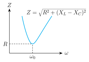
Plotted against frequency, Z falls to a minimum Z=R at the resonant frequency f0=2πLC1 and rises steeply on both sides (a U-shaped curve).
(b) Phase difference at resonance. At resonance XL=XC; VL leads the current by 90∘ and VC lags by 90∘, so the phase difference between them is 180∘.
(c) DC vs AC. For DC (f=0) the inductor offers only its resistance: R=1200=200Ω. For AC it also offers reactance, so Z=0.5200=400Ω. Then …
(a) Series-LCR impedance Z=R2+(XL−XC)2 is minimum (=R) at resonance; at resonance VL and VC are 180∘ out of phase; the inductor's L=π23≈1.10 H.
(b) A step-down transformer lowers ac voltage; for the transmission line the current is 300 A, line resistance 20 Ω, so the power lost as heat is 1800 kW.
Part (a)
Impedance of a series LCR circuit
The resistor opposes current by R; the inductor by XL=ωL (rising with frequency); the capacitor by XC=1/ωC (falling with frequency). Because VL leads and VC lags the current by 90∘, they are 180∘ apart and combine as ∣XL−XC∣. Phasor addition of VR (along the current) with (VL−VC) gives
V0=I0R2+(XL−XC)2 ⇒ Z=R2+(ωL−ωC1)2.
Variation with frequency. At ω→0, XC→∞ so Z→∞; as ω rises XC falls and XL rises until, at ω0=1/LC, XL=XC and Z=R (minimum); beyond resonance XL>XC and Z rises again. The plot of Z versus f is a U-shaped curve with its minimum R at f0=2πLC1.
(b) Phase difference at resonance …
Showing the 12 most recent of 47 on this concept.
- CBSE 2026Set 55/1/11 markMCQQ.In a series LCR circuit, the voltage across the resistor, capacitor and inductor is 10 V each. If the capacitor is short circuited, the voltage across the inductor will be (A) 10 V (B) 52 V (C) 25 V (D) 102 V
›Reveal solutionSolution
In a series LCR circuit, when each component drops 10 V, the source voltage is 10 V (since VC and VL cancel) and the equal drops imply XL=XC=R. Shorting the capacitor leaves an RL circuit of impedance R2, so the current becomes I′=R210 and the inductor voltage is VL′=I′XL=210=52 V. The answer is (B).
Concept and intuition
The problem gives a series LCR circuit where the voltage across each element — resistor, capacitor, and inductor — is 10 V. That’s a strong clue: in a series circuit, the current is the same through all components, but the voltages are not in phase. The resistor voltage is in phase with current, the inductor voltage leads by 90°, and the capacitor voltage lags by 90°. So the three 10 V readings are phasor magnitudes, not simple arithmetic sums.
The key insight: if the capacitor is shorted, the circuit becomes a simple RL series circuit. The source voltage remains the same (it’s fixed by the supply), but the impedance changes. We need to find the new inductor voltage.
Step-by-step solution
1. Find the source voltage from the initial LCR condition.
In a series LCR circuit, the phasor sum of voltages across R, L, and C equals the source voltage Vs. Since VL and VC are opposite in phase (180° apart), they subtract. Given VR=VL=VC=10 V:
Vs=VR2+(VL−VC)2=102+(10−10)2=10 V
So the source supplies only 10 V. This makes sense: the inductor and capacitor voltages cancel exactly, so the source only “sees” the resistor drop.
TipThis cancellation is the hallmark of resonance in a series LCR circuit — at resonance, XL=XC, and the impedance is purely resistive. Here, VL=VC implies XL=XC, so the circuit is at resonance.
2. Determine the relationship between R and XL (or XC).
At resonance, the current is I=Vs/R=10/R. The voltage across the inductor is VL=IXL=(10/R)XL=10 V. Therefore:
R10XL=10⇒XL=R
So the inductive reactance equals the resistance. Similarly, XC=R as well. …
- CBSE 2026Set V11 markMCQQ.Power factor of a series LCR circuit is maximum when :(a) XL=XC(b) XC=0(c) XL>XC(d) XL<XC
›Reveal solutionSolution
- CBSE 2026Set ANNUAL1 markMCQQ.An ideal transformer has 500 turns in the primary and 5000 turns in the secondary. If the primary be connected to a 6 V battery, then the secondary voltage is(a) 0(b) 0.6 V(c) 60 V(d) 6 V
›Reveal solutionSolution
A transformer needs a changing current/flux to work. A DC battery gives a constant current, so once steady state is reached the secondary voltage is 0.
A transformer works on the principle of mutual induction: the emf induced in the secondary is
es=−Mdtdip
…
- CBSE 2026Set ANNUAL1 markQ.Why cannot a transformer be used to step up direct current (D.C.)?
›Reveal solutionSolution
No changing flux, no induced EMF — a transformer needs AC to work at all.
A transformer operates on the principle of mutual induction: a time-varying current in the primary coil produces a time-varying magnetic flux in the core, which links the secondary coil and induces an EMF in it, given by ε2=−N2dtdΦ. With a constant DC current in the primary, the flux in the core, once established, remains steady (constant) — its rate of change dΦ/dt is zero in the steady state. Since the induced EMF depends entirely on this rate of change, no EMF (and hence no stepped-up voltage) is induced in the secondary for steady DC, so a t …
- CBSE 2026Set ANNUAL1 markQ.Write True or False: The quality factor is ω_r L / R.
›Reveal solutionSolution
True — for a series resonant circuit, Q = ω_r L / R.
The quality factor (Q-factor) of a series resonant LCR circuit measures the sharpness of resonance. It is defined as the ratio of the inductive reactance at resonance to the resistance:
Q = ω_r L / R = (1/R)√(L/C),
…
- CBSE 2026Set SEM31 markMCQQ.The condition of getting maximum current in an LCR series circuit is(a) X_L = 0(b) X_C = 0(c) X_L = X_C(d) R = X_L − X_C
›Reveal solutionSolution
A series LCR circuit carries maximum current at resonance, where the inductive and capacitive reactances are equal (X_L = X_C), leaving impedance Z = R minimum. Option (c).
Step 1 — impedance of a series LCR circuit: Z = √(R² + (X_L − X_C)²), from NCERT/CBSE Class 12 Physics, Alternating Current.
…
- CBSE 2025Set X11 markMCQQ.Transformer cores are usually laminated. This is to reduce energy loss due to(a) flux leakage(b) winding resistance(c) eddy currents(d) hysteresis
›Reveal solutionSolution
(c) eddy currents. The changing flux in the core induces circulating (eddy) currents in the solid metal, which dissipate energy as heat (∝ resistance path). Laminating the core with thin i …
- CBSE 2025Set D1 markMCQQ.In resonance condition, the frequency of L-C circuit is (A) (1/2π)√(1/LC) (B) 2π√(1/LC) (C) 2π√(LC) (D) (1/2π)√(LC)
›Reveal solutionSolution
At resonance the inductive and capacitive reactances are equal, giving the natural frequency f = 1/(2π√(LC)).
Resonance in an L-C (or series L-C-R) circuit occurs when the inductive reactance equals the capacitive reactance:
XL=XC ⇒ ωL=ωC1
Solving for the angular frequency,
…
- CBSE 2025Set ANNUAL1 markMCQQ.Which quantity is increased in a step-up transformer ?(a) current(b) voltage(c) power(d) frequency
›Reveal solutionSolution
A step-up transformer increases voltage (and correspondingly decreases current), since power and frequency stay the same.
For an ideal transformer,
VpVs=NpNs …
- CBSE 2025Set ANNUAL1 markQ.On which principle does transformer work?
›Reveal solutionSolution
A transformer transfers energy from primary to secondary coil through mutual induction of a changing magnetic flux.
A transformer consists of two coils (primary and secondary) wound on a common laminated soft-iron core. When an alternating current is passed through the primary coil, it produces a continuously changing magnetic flux in the core. Since the secondary coil is linked to the same core, this changing flux also links the secondary coil.
By Faraday's law of electromagnetic induction, a changing flux linked with the secondary coil induces an alternating emf in it — this is mutual induction, i.e., induction of emf in one coil due to a changing current in a nearby (magnetically coupled) coil.
…
- CBSE 2025Set ANNUAL1 markMCQQ.A series LCR circuit fed by an ac source with angular frequency ω acts as a purely resistive circuit, when(a) ωL > 1/ωC(b) ωL < 1/ωC(c) ωL = 1/ωC(d) ω³L = 1/ωC²
›Reveal solutionSolution
A series LCR circuit behaves as purely resistive at resonance, when the inductive and capacitive reactances cancel.
The impedance of a series LCR circuit is
Z=R2+(ωL−ωC1)2 …
- CBSE 2025Set ANNUAL1 markQ.Why is electric power transmission from power stations to sub-stations near consumers done at high voltages ?
›Reveal solutionSolution
For a fixed power to be delivered, P=VI, so raising the transmission voltage lowers the current; since resistive line loss goes as I2R, a lower current means far less energy is wasted as heat.
Electrical power transmitted is P=VI. For a given power P to be delivered by the transmission line, increasing the transmission voltage V proportionally decreases the current I=P/V.
The power dissipated as heat in the transmission line's resistance R is
Ploss=I2R
…
🎓Unlock everything free for 14 days
- ✓Full step-by-step solutions
- ✓Concept-first explanations
- ✓Methods, shortcuts & mistakes
- ✓PYQ mapping + timed mock tests
Full access for 14 days. No credit card required.