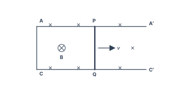
Q.(a) Derive the expression for the torque acting on the rectangular current carrying coil of a galvanometer. Why is the magnetic field made radial ?
🔒You're viewing a preview — the full solution, concept, methods & PYQ mapping are locked.
🔒 Start your 14-day free trial to unlock the full solution →Part (a)Concept understanding — Moving Coil Galvanometer
Moving Coil Galvanometer: From Intuition to Formula
Imagine you have a tiny, lightweight coil of wire, suspended so it can rotate freely. If you pass a current through it, that coil becomes an electromagnet. Now place it between the poles of a strong permanent magnet. The coil will try to twist — it experiences a torque. The bigger the current, the harder it twists. That is the entire physical idea behind a moving coil galvanometer: use a current to produce a rotation, and measure the rotation to know the current.
But a freely spinning coil would just keep turning. To get a useful measurement, you need something that opposes that rotation — a restoring force that grows as the coil turns further. That is the job of a spring (usually a fine phosphor-bronze strip called a torsion fibre). The spring twists as the coil rotates, producing a restoring torque that exactly balances the magnetic torque at some angle. That equilibrium angle is your reading.
The Radial Magnetic Field — The Key Trick
Here is the clever part. If the magnetic field were uniform and the coil rotated out of alignment, the torque would change with angle — making the scale non-linear. To avoid that, the poles of the magnet are shaped into concave cylindrical surfaces, and a soft iron cylinder is placed inside the coil. This creates a radial magnetic field: the field lines always point radially outward (or inward), so the plane of the coil is always parallel to the field as it rotates.
In a radial field, the magnetic torque on the coil is independent of the coil's angular position. The torque depends only on the current.
That is what makes the deflection directly proportional to current — a linear scale.
The Physics in Equations
Let the coil have N turns, each of area A. A current I flows through it. The magnetic field strength is B (radial). The torque due to the magnetic field on a single turn is:
τm=NIAB
This is because the force on each vertical side of the coil is ILB (where L is the length of the side), and the lever arm is the width of the coil, so the product gives I×(area)×B per turn.
The spring provides a restoring torque proportional to the twist angle θ:
τs=kθ
where k is the torsion constant of the spring (unit: N·m/rad).
At equilibrium, the two torques balance:
NIAB=kθ
So the deflection is:
θ=kNABI
The quantity kNAB is called the current sensitivity of the galvanometer. It tells you how many radians of deflection you get per ampere of current.
θ=(kNAB)I
What This Means for a Student
- Larger N, A, or B makes the galvanometer more sensitive — more deflection for the same current. …
Part (b)Concept understanding — Transformer Principle
Transformer Principle: From Intuition to Precision
Imagine you have a water pipe with a narrow section and a wide section. Water flows through the narrow part fast but with low pressure; through the wide part it flows slow but with high pressure. The total amount of water (flow × pressure) stays the same. A transformer does something similar — but for electricity.
A transformer takes AC power at one voltage and current, and delivers nearly the same power at a different voltage and current. If voltage goes up, current must come down, and vice versa. The total power (voltage × current) is almost unchanged — minus a tiny loss.
The Core Idea: Mutual Induction
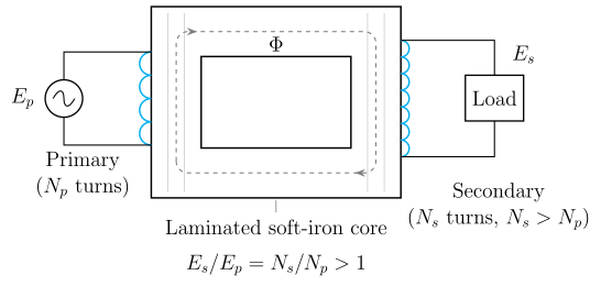
Two coils of wire are placed near each other, usually wound around a common iron core. When AC flows through the first coil (the primary), it creates a changing magnetic field. That changing field passes through the second coil (the secondary) and induces a voltage across it. This is mutual induction — a changing current in one coil induces a voltage in a neighbouring coil.
The iron core is crucial: it guides the magnetic field from one coil to the other with very little leakage, making the transfer efficient.
A transformer works only with AC. A steady DC current produces a constant magnetic field, which induces nothing in the secondary coil. Change is essential.
The Precise Statement
For an ideal transformer (no energy losses), the relationship between primary and secondary voltages and currents is:
VpVs=NpNsandIpIs=NsNp
where:
- Vp, Vs = primary and secondary voltages
- Ip, Is = primary and secondary currents
- Np, Ns = number of turns in primary and secondary coils
VpIp=VsIs
Power in equals power out (ideal case).
What This Means
If the secondary has more turns than the primary (Ns>Np), the secondary voltage is higher — this is a step-up transformer. Current in the secondary is correspondingly lower.
If the secondary has fewer turns (Ns<Np), the secondary voltage is lower — a step-down transformer. Current in the secondary is higher.
A step-up transformer raises voltage but lowers current. It does not create energy. The product V×I stays constant (ignoring losses). Many beginners think a step-up transformer "amplifies" power — it does not.
Why the Turns Ratio Works
The voltage induced in each turn of a coil is the same (because the same changing magnetic flux links every turn). So the total induced voltage is proportional to the number of turns:
Vp∝Np,Vs∝Ns
Dividing gives the ratio. For current, conservation of power forces the inverse relationship.
A Real Transformer: Small Losses …
Part (a)
Galvanometer torque. A rectangular coil of N turns, area A=lb, carries current I in field B. The two sides of length l feel forces F=BIl forming a couple. If the coil normal makes angle θ with B, the torque is
τ=NBIl(bsinθ)=NBIAsinθ.
The field is made radial (concave pole pieces + soft-iron core) so the plane of the coil is always along B, i.e. θ=90∘ at every deflection, giving τ=NBIA (constant). This makes deflection ∝I — a linear scale.
α-particle radius. q=2e=3.2×10⁻¹⁹ C. From qV=21mv2, v=2qV/m=6.4×10−272⋅3.2×10−19⋅104=106 m/s. …
Part (a): torque on a galvanometer coil is τ=NBIAsinθ; a radial field keeps θ=90∘ so τ=NBIA is constant (linear scale); the α-particle moves in a circle of radius r=B12mV/q=10 m.
Part (b): a step-up transformer works by mutual induction, Es/Ep=Ns/Np; laminated core cuts eddy currents and thick copper cuts I2R loss; the sliding rod needs F=B2l2v/R=6.4×10−3 N and power 6.4×10⁻⁴ W.
Part (a) — Galvanometer torque and α-particle path
Torque derivation. Rectangular coil, N turns, sides l (parallel to the axis) and b, area A=lb, current I, field B. Each length-l side experiences F=BIl; the pair forms a couple. With the coil normal at angle θ to B, the arm of the couple is bsinθ, so for N turns
τ=N(BIl)(bsinθ)=NBIAsinθ,τ=NIA×B.
Why a radial field? Curved (concave) pole pieces with a soft-iron cylindrical core make the field radial, so the plane of the coil always contains B and θ=90∘ for every position. Then τ=NBIA (maximum and constant). Balancing the spring torque kϕ:
NBIA=kϕ⇒ϕ=kNBIA∝I,
giving a uniform (linear) scale.
α-particle radius. Charge q=2e=3.2×10⁻¹⁹ C, m=6.4×10⁻²⁷ kg, V=104 V, B=2×10⁻³ T.
qV=21mv2⇒v=m2qV=6.4×10−272(3.2×10⁻¹⁹)(104)=1012=106 m/s. …
Showing the 12 most recent of 32 on this concept.
- CBSE 2026Set 55/3/11 markMCQQ.Assertion (A) : The cylindrical soft iron core in a moving coil galvanometer only makes the magnetic field radial and does not affect the strength of the magnetic field. Reason (R) : In a moving coil galvanometer, the plane of the coil is always perpendicular to the magnetic field. (A) Both Assertion (A) and Reason (R) are true and Reason (R) is the correct explanation of the Assertion (A). (B) Both Assertion (A) and Reason (R) are true, but Reason (R) is not the correct explanation of the Assertion (A). (C) Assertion (A) is true, but Reason (R) is false. (D) Both Assertion (A) and Reason (R) are false.
›Reveal solutionSolution
The soft iron core makes the field radial AND, being ferromagnetic, concentrates the magnetic flux — it increases the field strength, so the Assertion is false. In a radial field the plane of the coil is always parallel to the field lines (the coil's normal is perpendicular to B), so the Reason is also false. The correct option is (D).
The question tests two separate facts about the moving coil galvanometer: what the cylindrical soft iron core actually does, and how the coil sits relative to the magnetic field.
1. Role of the soft iron core — is the Assertion true?
The core, together with the concave pole pieces, shapes the field in the air gap so that it is radial: at every angular position of the coil, the field lines point along the radius. This makes the deflecting torque independent of the coil's position, which is what gives the galvanometer its linear scale θ∝I.
But that is not all the core does. Soft iron is ferromagnetic, with a very high relative permeability (μr≫1). It provides a low-reluctance path for the magnetic flux, so the flux crowds through the core and the field strength B in the narrow air gap becomes much larger than it would be without the core. The claim that the core "only makes the field radial and does not affect the strength" is therefore false — the Assertion is false.
2. Orientation of the coil — is the Reason true?
In the radial field the field lines run along the radius, and the plane of the rectangular coil (tangential to the cylindrical core) always contains those field lines. So the plane of the coil is always parallel to the magnetic field — equivalently, the coil's normal is perpendicular to B in every position. That is exactly what keeps the torque at its maximum value throughout the rotation: …
- CBSE 2026Set ANNUAL1 markMCQQ.An ideal transformer has 500 turns in the primary and 5000 turns in the secondary. If the primary be connected to a 6 V battery, then the secondary voltage is(a) 0(b) 0.6 V(c) 60 V(d) 6 V
›Reveal solutionSolution
A transformer needs a changing current/flux to work. A DC battery gives a constant current, so once steady state is reached the secondary voltage is 0.
A transformer works on the principle of mutual induction: the emf induced in the secondary is
es=−Mdtdip
…
- CBSE 2026Set ANNUAL1 markQ.Why cannot a transformer be used to step up direct current (D.C.)?
›Reveal solutionSolution
No changing flux, no induced EMF — a transformer needs AC to work at all.
A transformer operates on the principle of mutual induction: a time-varying current in the primary coil produces a time-varying magnetic flux in the core, which links the secondary coil and induces an EMF in it, given by ε2=−N2dtdΦ. With a constant DC current in the primary, the flux in the core, once established, remains steady (constant) — its rate of change dΦ/dt is zero in the steady state. Since the induced EMF depends entirely on this rate of change, no EMF (and hence no stepped-up voltage) is induced in the secondary for steady DC, so a t …
- CBSE 2025Set X11 markMCQQ.Transformer cores are usually laminated. This is to reduce energy loss due to(a) flux leakage(b) winding resistance(c) eddy currents(d) hysteresis
›Reveal solutionSolution
(c) eddy currents. The changing flux in the core induces circulating (eddy) currents in the solid metal, which dissipate energy as heat (∝ resistance path). Laminating the core with thin i …
- CBSE 2025Set D1 markMCQQ.If the number of turns is increased in any moving coil galvanometer, then its sensitivity (A) increases (B) decreases (C) remains unchanged (D) may increase or may decrease
›Reveal solutionSolution
A galvanometer's current sensitivity is (NAB/k), directly proportional to the number of turns N, so more turns → higher sensitivity.
The deflection of a moving-coil galvanometer is
θ=kNABI
so its current sensitivity is
Iθ=kNAB
…
- CBSE 2025Set ANNUAL1 markMCQQ.Which quantity is increased in a step-up transformer ?(a) current(b) voltage(c) power(d) frequency
›Reveal solutionSolution
A step-up transformer increases voltage (and correspondingly decreases current), since power and frequency stay the same.
For an ideal transformer,
VpVs=NpNs …
- CBSE 2025Set ANNUAL1 markQ.On which principle does transformer work?
›Reveal solutionSolution
A transformer transfers energy from primary to secondary coil through mutual induction of a changing magnetic flux.
A transformer consists of two coils (primary and secondary) wound on a common laminated soft-iron core. When an alternating current is passed through the primary coil, it produces a continuously changing magnetic flux in the core. Since the secondary coil is linked to the same core, this changing flux also links the secondary coil.
By Faraday's law of electromagnetic induction, a changing flux linked with the secondary coil induces an alternating emf in it — this is mutual induction, i.e., induction of emf in one coil due to a changing current in a nearby (magnetically coupled) coil.
…
- CBSE 2025Set ANNUAL1 markQ.Why is electric power transmission from power stations to sub-stations near consumers done at high voltages ?
›Reveal solutionSolution
For a fixed power to be delivered, P=VI, so raising the transmission voltage lowers the current; since resistive line loss goes as I2R, a lower current means far less energy is wasted as heat.
Electrical power transmitted is P=VI. For a given power P to be delivered by the transmission line, increasing the transmission voltage V proportionally decreases the current I=P/V.
The power dissipated as heat in the transmission line's resistance R is
Ploss=I2R
…
- CBSE 2024Set 55/2/11 markMCQQ.Which of the following quantity/quantities remains same in primary and secondary coils of an ideal transformer ? Current, Voltage, Power, Magnetic flux (A) Current only (B) Voltage only (C) Power only (D) Magnetic flux and Power both
›Reveal solutionSolution
In an ideal transformer, the magnetic flux linking both coils is the same (by Faraday’s law), and power is conserved (no losses). Current and voltage change with the turns ratio. So the correct choice is (D) Magnetic flux and Power both.
The core idea
An ideal transformer is a perfect magnetic circuit with no energy losses — no resistance in the windings, no hysteresis, no eddy currents, and perfect coupling (all flux from the primary passes through the secondary).
Two fundamental principles govern it:
- Faraday’s law of induction — the same changing magnetic flux Φ links every turn of both coils.
- Conservation of energy — in the absence of losses, the power delivered to the primary must equal the power extracted from the secondary.
From these, everything else follows.
Step-by-step reasoning
- Magnetic flux is the same in both coils In an ideal transformer, the core is assumed to have zero reluctance and no flux leakage. The alternating current in the primary creates a time-varying magnetic flux Φ(t) that is entirely confined to the core. Since both coils are wound on the same core, every turn of the secondary is linked by exactly the same flux as every turn of the primary. By Faraday’s law, the induced emf in each coil is proportional to the number of turns:
Ep=−NpdtdΦ,Es=−NsdtdΦ
The flux Φ itself is identical — only the induced voltages differ because Np=Ns.
- Voltage changes with the turns ratio From the above,
VpVs=NpNs
So voltage is not the same in primary and secondary unless Np=Ns (which is not generally true).
- Current changes inversely with the turns ratio For an ideal transformer, the magnetising current is negligible, and the primary current adjusts to balance the secondary load. Power conservation gives:
VpIp=VsIs⇒IpIs=NsNp
So current is also not the same.
- Power is conserved …
- CBSE 2024Set ANNUAL1 markMCQQ.In any electric circuit, galvanometer in its original form is used to -(a) detect the current(b) measure the current(c) measure the voltage(d) measure the resistance
›Reveal solutionSolution
A galvanometer in its basic form is a sensitive current-detecting device, not a calibrated measuring instrument.
A galvanometer is a sensitive instrument used to detect the presence (and direction) of a small current in a circuit through the deflection of a coil/needle. In its original form it is not calibrated to read numerical values of current, voltage o …
- CBSE 2024Set IMPROVEMENT1 markMCQQ.In actual transformer, reason of energy losses is —(a) Flux Leakage(b) Eddy Currents(c) Resistance of the windings(d) All of above
›Reveal solutionSolution
A real transformer loses energy through flux leakage, eddy currents, AND winding resistance — all three act together.
An ideal transformer has no losses, but an actual transformer loses energy due to: (1) Flux leakage — not all of the flux produced by the primary links the secondary. (2) Eddy currents induced in the iron core, which dissipate energy as heat (reduced, but not eliminated, by lamination). (3) Resistance of the copper windin …
- CBSE 2024Set A1 markMCQQ.The value of current obtained in a moving coil galvanometer is proportional to (A) deflection (θ) (B) resistance (R) (C) magnetic field (B) (D) none of these
›Reveal solutionSolution
A moving-coil galvanometer is linear: I ∝ θ (the deflection).
In a moving-coil galvanometer, the current-carrying coil in the radial magnetic field experiences a deflecting torque NBIA, balanced by the restoring torque kθ of the suspension:
NBIA=kθ⇒I=NBAkθ.
…
🎓Unlock everything free for 14 days
- ✓Full step-by-step solutions
- ✓Concept-first explanations
- ✓Methods, shortcuts & mistakes
- ✓PYQ mapping + timed mock tests
Full access for 14 days. No credit card required.