Q.(a) Explain the statement: "Current is a scalar although we represent current with an arrow".
You're viewing a preview — the full solution, concept, methods & PYQ mapping are locked.
Start your 14-day free trial to unlock the full solution →Current is a scalar because it obeys algebraic addition at junctions, not vector addition. Using the node-voltage method (a direct application of Kirchhoff's rules), the current through the resistor is , flowing upward from E to B.
Part (a): Why current is a scalar despite the arrow
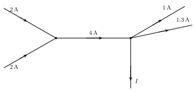
When we draw an arrow next to a current , it is tempting to think of current as a vector. But here is the crucial distinction: a vector quantity must obey the parallelogram law of addition. If you have two currents meeting at a junction, you simply add them algebraically — — not by constructing a parallelogram. The arrow on a circuit diagram is merely a sign convention: it tells you which direction we call positive for that branch. The actual magnitude is a number, and the direction is captured by the sign of that number in the equations.
A common mistake is to treat current as a vector and try to resolve it into components. In a wire, current has only two possible directions (forward or backward), so a single signed number suffices — this is the hallmark of a scalar.
Part (b): Finding the current through the resistor
We will use the node-voltage method, which is Kirchhoff's current law (KCL) applied at a single node. This is often faster than writing multiple loop equations.
1. Label the nodes and choose a reference.
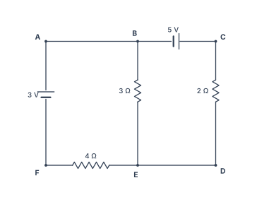
The circuit has six labelled nodes: A, B, C (top row) and F, E, D (bottom row). Notice that A–B is a plain wire, so . Similarly, E–D is a plain wire, so . Let us take node F as the reference (ground): .
2. Determine the voltages fixed by the batteries.
The cell in the left branch has its positive plate at A (toward A) and negative plate at F. Since , this means . And because A–B is a wire, as well.
The cell in the top branch has its negative plate at B and positive plate at C. So .
Always check the orientation of the battery: the positive terminal is the longer line in the symbol. The voltage rises from the negative to the positive terminal.
3. Identify the unknown node voltage.
The only node whose voltage we do not yet know is E (and D, since they are connected by a wire). Let .
4. Apply Kirchhoff's current law at node E.
Three branches meet at E:
- The resistor from B to E: current (flowing from B to E if ).
- The resistor from C to D: current (flowing from C to D if ). …
Unlock everything free for 14 days
- Full step-by-step solutions
- Concept-first explanations
- Methods, shortcuts & mistakes
- PYQ mapping + timed mock tests
Full access for 14 days. No credit card required.