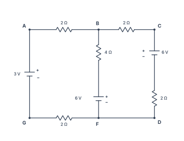
Q.The figure shows a circuit with three ideal batteries. Find the magnitude and direction of currents in the branches AG, BF and CD.
You're viewing a preview — the full solution, concept, methods & PYQ mapping are locked.
Start your 14-day free trial to unlock the full solution →Using Kirchhoff's laws, the three branch currents are found by setting up two loop equations and one junction equation. The currents are: from A to G, from B to F, and from C to D.
Concept and Intuition
This is a classic three-loop circuit with ideal batteries — meaning they have no internal resistance, so each battery simply supplies its rated voltage regardless of current. The trick is that the branches are not independent: the current through AG also flows through the top rail AB and the bottom rail GF (they're all in series). Similarly, the current through CD flows through the top rail BC. The middle branch BF shares current with both.
Kirchhoff's current law (KCL) at junction B tells us how the three branch currents relate. Kirchhoff's voltage law (KVL) around two independent loops gives two more equations. Three unknowns, three equations — solvable.
A common mistake is to treat the 2 Ω resistors in the top and bottom rails as separate from the branches. They are in series with the branch currents, so they must be included in the loop equations with the correct current.
Step-by-Step Solution
1. Label the currents and assign directions.
Let:
- = current in branch AG (flowing from A to G, through the 3 V battery, then through the 2 Ω resistor in AG, then through the 2 Ω resistor in GF, and back to B)
- = current in branch BF (flowing from B to F through the 4 Ω resistor and 6 V battery)
- = current in branch CD (flowing from C to D through the 6 V battery and 2 Ω resistor)
We'll assume these directions. If a current comes out negative, it means the actual direction is opposite.
2. Apply KCL at junction B.
The current entering B from the left (through the 2 Ω resistor from A) is . The currents leaving B are (down through BF) and (right through BC, then down through CD). So:
3. Apply KVL to the left loop (A–G–F–B–A).
Go clockwise starting at A. From A to G, we cross the 3 V battery from its positive terminal (A) to its negative terminal (G), a voltage drop of . From G to F, current flows through the 2 Ω resistor in the direction of travel, a drop of . From F to B, we cross the 4 Ω resistor (current , drop ) and then the 6 V battery from its negative to positive terminal, a rise of 6 V (i.e. a drop of ). Finally, from B back to A, current flows through the 2 Ω resistor in the direction of travel, a drop of .
Sum of voltage drops around the loop = 0:
Simplify:
4. Apply KVL to the right loop (B–F–D–C–B). …
Unlock everything free for 14 days
- Full step-by-step solutions
- Concept-first explanations
- Methods, shortcuts & mistakes
- PYQ mapping + timed mock tests
Full access for 14 days. No credit card required.