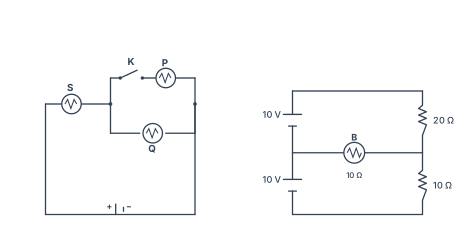
Q.(a) In the given figure, three identical bulbs P, Q and S are connected to a battery.
🔒You're viewing a preview — the full solution, concept, methods & PYQ mapping are locked.
🔒 Start your 14-day free trial to unlock the full solution →Part (a)Concept understanding — Kirchhoff's Current and Voltage Rules
Why Ohm's law alone is not enough. Ohm's law, V=IR, is directly useful only for simple, single-loop circuits with a single emf source. Real circuits frequently contain multiple loops, multiple junctions, and sometimes multiple emf sources, for which Kirchhoff's two generalised rules provide a complete and systematic method of analysis.
Kirchhoff's first rule (current rule / junction rule). At any junction of a circuit, the algebraic sum of the currents is zero -- current entering the junction is taken as positive, current leaving as negative. This is a direct statement of the conservation of electric charge: whatever charge flows into a junction in a given time must also flow back out, since charge cannot accumulate or vanish at a point. For a junction with several currents I1,…,I5 meeting it, the rule reads I1+I2−I3−I4−I5=0, i.e. total current in equals total current out.
Kirchhoff's second rule (voltage rule / loop rule). In any closed loop of a circuit, the algebraic sum of the IR products (voltage drops across resistors) and emfs around that loop is zero. This follows from the conservation of energy: the total energy supplied by every emf source around the loop must equal the total energy delivered to every resistor in that loop. The sign convention is essential: an IR term is positive when the loop is traversed in the SAME direction as the assumed current, negative when traversed against it; an emf is positive when traversed from the cell's negative to positive terminal, negative the other way. The voltage rule may only be validly applied once every current in the circuit has reached a steady state (no longer changing in time). …
Part (b)Concept understanding — Power Dissipation in Resistors
Power Dissipation in Resistors
Whenever charge is driven through a resistor, electrical energy is converted into heat. The rate of this conversion is the power dissipated.
Why a Resistor Heats Up
Inside a resistor, drifting electrons repeatedly collide with the vibrating lattice ions. Each collision transfers kinetic energy to the lattice, raising its temperature. The source (battery or AC supply) continually does work to keep the current flowing, and that work reappears as heat. This is Joule heating.
The Power Formulas (DC)
The power delivered to any device carrying current I across a potential difference V is
P=VI
For an ohmic resistor V=IR, so this can be written in three equivalent forms:
P=VI=I2R=RV2
The SI unit is the watt (W), where 1 W=1 J s−1.
Which form to use depends on what is fixed:
- Series elements share the same current, so P=I2R shows the larger resistor dissipates more.
- Parallel elements share the same voltage, so P=V2/R shows the smaller resistor dissipates more.
The total heat produced in time t is Q=Pt=I2Rt — Joule's law of heating.
Power Dissipation with AC
With alternating current the instantaneous power p(t)=i2(t)R fluctuates, but a resistor still only dissipates energy (it never returns any). The average power over a cycle is written with root-mean-square values:
Pavg=Irms2R=RVrms2=VrmsIrms
where for a sinusoid Irms=Im/2 and Vrms=Vm/2. This is precisely why rms values are defined: an AC of rms value Irms heats a resistor at the same average rate as a steady DC of value Irms.
A pure resistor has power factor 1 — voltage and current are in phase, so all the power supplied is dissipated. In inductors and capacitors, by contrast, the average dissipated power is zero; energy is only stored and returned.
Worked Example
A 100 Ω resistor carries a current of 0.5 A. …
Why this formula?
Power Dissipation in Resistors — Why the Formula Holds
Let's build this from first principles. The goal is to understand why a resistor dissipates power as heat, and how the formula P=I2R (and its equivalents) arise naturally.
1. What is "Power" in an Electrical Circuit?
Power is the rate of energy transfer — how much energy is converted from one form to another per unit time.
- In a resistor, electrical energy is converted into heat (thermal energy).
- The fundamental definition of electrical power is:
P=V⋅I
where:
- P = power (watts, W)
- V = voltage across the component (volts, V)
- I = current through the component (amperes, A)
Why this definition?
Voltage is energy per unit charge (V=qW), and current is charge per unit time (I=tq). Multiplying them gives energy per unit time — exactly power.
2. How Does a Resistor Behave? — Ohm's Law
A resistor obeys Ohm's Law:
V=I⋅R
where R is resistance (ohms, Ω). This is an empirical law — it describes how real resistors behave: the voltage across them is proportional to the current through them.
3. Deriving the Power Dissipation Formulas
We start with P=VI and substitute Ohm's Law in two ways.
Case A: Express power in terms of I and R
Replace V with IR:
P=(IR)⋅I=I2R
Interpretation:
- For a fixed resistance, power grows with the square of current.
- Doubling current quadruples the heat generated — this is why high currents cause wires to overheat.
Case B: Express power in terms of V and R
Replace I with RV:
P=V⋅(RV)=RV2
Interpretation:
- For a fixed voltage, power is inversely proportional to resistance.
- A low-resistance resistor (like a short circuit) dissipates huge power at a given voltage — that's why short circuits are dangerous.
4. The Physical "Why" — Energy Conversion at the Atomic Level
Why does this energy turn into heat?
- Electrons moving through a resistor collide with the atoms of the material.
- Each collision transfers kinetic energy from the electron to the atom, making the atom vibrate more — i.e., heating up the resistor.
- The rate at which this energy is lost by the electrons (and gained by the lattice) is exactly P=I2R.
Key insight:
The I2 term appears because:
- More current = more electrons per second. …
Part (a)
S is in series with the parallel pair P∥Q, and key K is in series with P. Each identical bulb has resistance R; brightness ∝ power =I2R.
(i) K closed. P∥Q=R/2, total =3R/2, so IS=3R2V and IP=IQ=3RV. Then PS=IS2R=9R4V2 while PP=PQ=9RV2 → S is four times as bright as P or Q; P and Q are equally bright. …
- With K closed S glows four times as brightly as P or Q (which are equal); with K open S and Q are equally bright.
- The current through the bulb is 0.2 A.
Part (a)
From the circuit, S is in series with the parallel combination P∥Q, and K is in series with P. Let each identical bulb have resistance R and the battery emf be V; brightness ∝ power =I2R.
(i) Key K closed. Both P and Q conduct: P∥Q=R/2, total resistance =R+2R=23R.
IS=3R/2V=3R2V,IP=IQ=2IS=3RV.
PS=IS2R=9R4V2,PP=PQ=IP2R=9RV2.
So S carries twice the current of each parallel bulb and dissipates four times the power: S is the brightest (4×), while P and Q are equally bright. …
Showing the 12 most recent of 24 on this concept.
- CBSE 2026Set 55/1/11 markMCQQ.Two heaters rated as (P1,V) and (P2,V) are connected in series across a dc source of 2V volt. The power consumed by the combination will be (A) (P1+P2) (B) 2P1+P2 (C) 2(P1+P2)P1P2 (D) 4(P1+P2)P1P2
›Reveal solutionSolution
Each heater's resistance is found from its rated power and voltage; in series across 2V, the total power dissipated is 4(P1+P2)P1P2.
Why this approach works
When a device is rated at (P,V), it means that at voltage V it consumes power P. This rating tells us the device's resistance through P=RV2, so R=PV2. Once we know the resistances, we can treat the heaters as ordinary resistors in a series circuit and calculate the actual power consumed at the new operating voltage.
The key insight: rated values describe behavior at a specific voltage, but resistance is an intrinsic property that doesn't change. We extract the resistance from the rating, then analyze the actual circuit.
Step-by-step solution
-
Find the resistance of each heater from its rating.
For heater 1 rated at (P1,V):
R1=P1V2
For heater 2 rated at (P2,V):
R2=P2V2
-
Calculate the total resistance in series.
When connected in series, resistances add:
Rtotal=R1+R2=P1V2+P2V2=V2(P11+P21)=V2⋅P1P2P1+P2
-
Apply the actual supply voltage.
The combination is connected across 2V. The power consumed by a resistor is:
P=RtotalVapplied2
Substituting:
P=V2⋅P1P2P1+P2(2V)2=V2⋅P1P2P1+P24V2
- Simplify the expression. …
-
- CBSE 2026Set 55/2/11 markMCQQ.Two statements are given – one labelled Assertion (A) and the other Reason (R). Select the correct answer from the codes below: (A) Both (A) and (R) are true and (R) is the correct explanation of (A). (B) Both (A) and (R) are true, but (R) is not the correct explanation of (A). (C) (A) is true, but (R) is false. (D) (A) is false and (R) is also false. Assertion (A) : Two electric heaters of power P1 and P2(>P1) are joined in series across a dc source of voltage V. The power consumed by the combination will be less than that consumed by P1 when connected across the same source. Reason (R) : The power consumed by an electric device when connected to a dc source of voltage V is proportional to its resistance.
›Reveal solutionSolution
The key idea is that in series, the combined resistance is larger than either heater's resistance, so the total power drawn from the source is smaller. The assertion is true; the reason is false because power is inversely proportional to resistance for a fixed voltage, not proportional.
Concept and intuition
When you connect a device to a fixed DC voltage source V, the power it consumes is given by P=V2/R. For a fixed voltage, power is inversely proportional to resistance — a higher resistance draws less current and therefore consumes less power. The reason statement gets this backwards.
Now, when two heaters are joined in series, their resistances add up. Since each heater's resistance is Ri=V2/Pi (from Pi=V2/Ri), the series combination has a total resistance Rseries=R1+R2, which is larger than either R1 or R2 alone. With a larger resistance, the power drawn from the same voltage source must be smaller than the power drawn by either individual heater. In particular, it will be less than P1 (the smaller power heater, which has the larger resistance). So the assertion is correct, but for a reason opposite to what is stated.
Step-by-step reasoning
- Express each heater's resistance in terms of its rated power. For a heater rated at power P when connected to voltage V, we have P=V2/R, so R=V2/P. Therefore:
R1=P1V2,R2=P2V2.
Since P2>P1, it follows that R2<R1 (higher power means lower resistance).
- Find the total resistance when they are in series.
Rseries=R1+R2=V2(P11+P21).
Clearly Rseries>R1 (and also >R2).
- Compute the power consumed by the series combination. Using P=V2/R again:
Pseries=RseriesV2=V2(P11+P21)V2=P11+P211=P1+P2P1P2.
- Compare Pseries with P1. Since P1>0, we have P1+P2>P2, so Pseries=P1+P2P1P2<P2P1P2=P1. …
- CBSE 2026Set ANNUAL1 markMCQQ.Kirchhoff's junction rule for electric circuits is based on which of the following physical quantities?(i) Mass(ii) Energy(iii) Electric charge(iv) None of these
›Reveal solutionSolution
Kirchhoff's junction (current) rule is just conservation of charge at a node.
Kirchhoff's junction rule states that the algebraic sum of currents meeting at a junction is zero (∑I=0). Since current is charge flow per unit time, this rule is a direct statement that charge can neither be cr …
- CBSE 2026Set ANNUAL1 markQ.The value of current 'I' in the given electric circuit will be ______ A.
›Reveal solutionSolution
By Kirchhoff's junction rule (conservation of charge), the total current entering a junction equals the total leaving it. Here 4.2 + 3.1 + 1.2 A flow in and 5.1 A + I flow out, so I = 8.5 − 5.1 = 3.4 A.
Kirchhoff's junction (current) rule states that the algebraic sum of currents at a junction is zero — equivalently, total current in = total current out, because charge cannot pile up.
From the figure, list the currents at the junction network:
- Entering: 4.2 A (from the left), 3.1 A (diagonally, from the upper-left), and 1.2 A (diagonally, from the upper-right).
- Leaving: 5.1 A (diagonally, toward the lower-right) and the unknown current I (to the right). …
- CBSE 2026Set ANNUAL1 markMCQQ.Kirchhoff's first law of electricity follow which conservation law?(a) Mass(b) Momentum(c) Energy(d) Charge
›Reveal solutionSolution
Kirchhoff's Current Law (junction rule) is a direct consequence of conservation of electric charge.
Kirchhoff's first law states that at any junction in a circuit, the algebraic sum of currents meeting at that junction is zero (∑Iin=∑Iout). Charge cannot accumulate at a junction in steady state, so whatever charge flows in per second must flow out per second — this is …
- CBSE 2025Set A1 markMCQQ.First law of Kirchhoff of current distribution follows —(i) Law of energy conservation(ii) Law of charge conservation(iii) Law of conservation of momentum(iv) Law of mass conservation
›Reveal solutionSolution
Kirchhoff's Current Law (junction rule) is a direct consequence of conservation of electric charge.
Kirchhoff's first law, also called the junction rule or current law, states that the sum of currents entering a junction in an electrical circuit equals the sum of currents leaving that junction (ΣI_in = ΣI_out), i.e. the algebraic sum of all currents at a junction is zero. Since current is the rate of flow of charge, and charge can neither be created nor destroyed at a junction (charge does not accumulate there in steady state …
- CBSE 2025Set ANNUAL1 markMCQQ.The algebraic sum of all the currents at any point in an electrical circuit is(a) positive(b) negative(c) zero(d) infinite
›Reveal solutionSolution
Kirchhoff's junction rule is a statement of conservation of charge: at any point (junction) in a circuit, charge cannot accumulate, so current flowing in must equal current flowing out.
If currents entering a junction are taken as positive and currents leaving as negative (or vice versa), then since no charge can pile up at a point in steady state:
…
- CBSE 2025Set ANNUAL1 markMCQQ.Kirchhoff's junction rule is reflection of:(a) conservation of current density vector.(b) the fact that the momentum with which a charged particle approaches a junction is unchanged as the charge particle leaves the junction.(c) conservation of charge and the fact that there is no accumulation of charges at a junction.(d) None of the above.
›Reveal solutionSolution
Kirchhoff's junction (current) rule follows directly from conservation of electric charge.
Kirchhoff's junction rule states that the algebraic sum of currents meeting at a junction in an electrical circuit is zero, i.e. the sum of currents entering a junction equals the sum of currents leaving it.
…
- CBSE 2025Set ANNUAL1 markMCQQ.If R1 and R2 are respectively the filament resistance of a 200 W bulb and a 100 W bulb designed to operate on the same voltage, then –(a) R1 = 2R2(b) R2 = 2R1(c) R2 = 4R1(d) R1 = 4R2
›Reveal solutionSolution
Since power P=V2/R at fixed voltage, the lower-power bulb has the higher filament resistance.
Both bulbs operate at the same voltage V. Using P=RV2, so R=PV2.
For the 200 W bulb: R1=200V2
For the 100 W bulb: R2=100V2=2002V2=2R1
…
- CBSE 2024Set A1 markMCQQ.Kirchhoff's second law of electricity is related to (A) conservation of mass (B) conservation of charge (C) conservation of energy (D) conservation of momentum
›Reveal solutionSolution
Kirchhoff's voltage (loop) law: sum of EMFs = sum of IR drops around a loop — a statement of energy conservation.
Kirchhoff's second law (the loop or voltage law) states that the algebraic sum of potential changes around any closed loop is zero: ∑ε=∑IR.
…
- CBSE 2024Set ANNUAL1 markMCQQ.Energy dissipated in LCR circuit is in(a) L only(b) C only(c) R only(d) All of these
›Reveal solutionSolution
Over a full AC cycle, a pure inductor and a pure capacitor store and release energy with zero net dissipation; only the resistive element genuinely converts electrical energy to heat.
In an LCR series circuit driven by an AC source, the current and voltage across L and C are 90 degrees out of phase with each other, so the average power delivered to a pure inductor or a pure capacitor over one complete cycle is zero:
PL=PC=0(average, over one cycle)
…
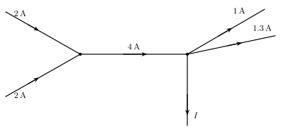
- CBSE 2024Set ANNUAL1 markMCQQ.The current I in the following circuit given below is(a) 1.7 A(b) 3.7 A(c) 1.3 A(d) 1A
›Reveal solutionSolution
Kirchhoff's current (junction) law: total current into a junction equals total current out; applying it at each junction of the circuit gives I = 1.7 A.
At the left junction, two branches each carrying 2 A flow in, so by charge conservation the single wire leaving that junction toward the right junction carries their sum: 2A+2A=4A.
…
🎓Unlock everything free for 14 days
- ✓Full step-by-step solutions
- ✓Concept-first explanations
- ✓Methods, shortcuts & mistakes
- ✓PYQ mapping + timed mock tests
Full access for 14 days. No credit card required.