Chemistry · Ch 9 — Coordination Compounds
Tetrahedral complexes
Tetrahedral complexes
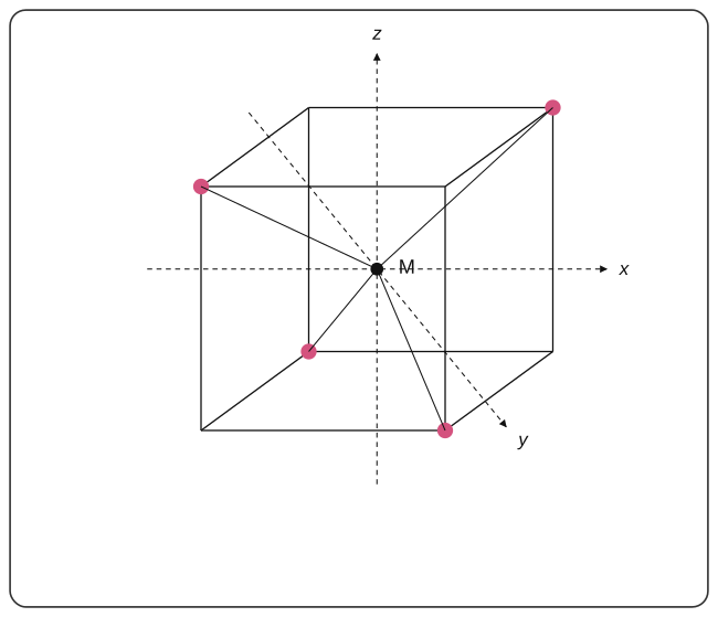
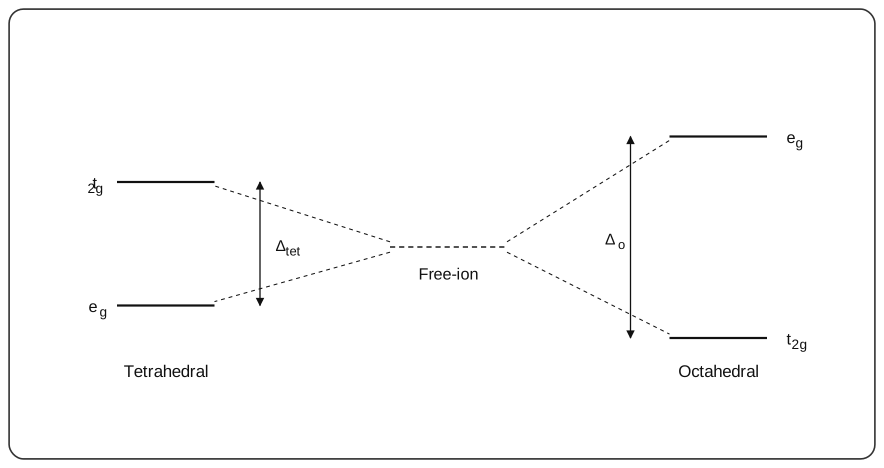
The pattern of d-orbital splitting predicted by CFT depends on the specific geometry of the surrounding ligand field, and the tetrahedral case gives a splitting pattern that is essentially the OPPOSITE of the octahedral one (Fig. 9.4 shows the tetrahedral geometry itself -- a central metal M with four ligands occupying the four corners of a tetrahedron, none of which lie directly along the x, y or z axes). In this tetrahedral arrangement, the three orbitals dxy, dyz and dzx (whose lobes lie diagonally, roughly pointing TOWARD where the ligands actually sit in a tetrahedral field) experience the GREATER repulsion and are pushed UP in energy; meanwhile dx2-y2 and dz2 (whose lobes lie more nearly BETWEEN the metal-ligand bond directions in this geometry) experience LESS repulsion and are pushed DOWN in energy -- exactly the reverse pairing of high-energy and low-energy orbital sets compared with the octahedral case (Fig. 9.5). Quantitatively, each electron placed in the higher-energy set (labelled simply t2 in a tetrahedral field, without the 'g' subscript used in the octahedral case, since a tetrahedron has no centre of symmetry) raises the total energy by 4 Dq, while each electron in the lower-energy set (labelled e) lowers it by 6 Dq. The overall magnitude of tetrahedral splitting, Delta-tet, works out to only about 4/9 of the equivalent octahedral splitting Delta-o for the same metal and ligands -- because in a tetrahedral arrangement, no single d orbital ever points directly at a ligand the way dz2 or dx2-y2 does along the axes in an octahedral field, so the repulsion (and hence the splitting) stays comparatively small throughout. Because Delta-tet is essentially always smaller than the electron-pairing energy, electron PAIRING is never energetically fa …
Drawn by us to help you understand the concept clearly, and verified to make sure it's accurate. For exams, practice from your textbook's own diagram.
What this figure shows. A central metal atom M sits at the centre of a tetrahedron, drawn with x, y and z axes passing through it; four ligands occupy the four corners of the tetrahedron, each corner lying between (not along) the coordinate axes, so no ligand approaches directly along any single x, y or z axis -- unlike the octahedral case where …
Drawn by us to help you understand the concept clearly, and verified to make sure it's accurate. For exams, practice from your textbook's own diagram.
What this figure shows. Three energy-level columns side by side. LEFT ('Free-ion'): the five d orbitals shown as one degenerate (unsplit) level. MIDDLE ('Octahedral'): split into the lower t2g set (three orbitals) and the upper eg set (two orbitals), separated by Delta-o, matching Fig. 9.2. RIGHT ('Tetrahedral'): split the OPPOSITE way -- a lower e set (two orbitals, dx2-y2/dz2) and an upper t2g-labelled set (three orbitals, dxy/dyz/dzx), separated by the visibly SMALLER gap Delta-tet (roughly 4/9 the size of Delta-o), illustrating both the reversed energy ordering and the much smaller splitting magnitude of the tetrahedral field compar …