Physics · Ch 13 — AC Circuits
Average Power in LCR Circuit (Power Factor)
Average Power in LCR Circuit (Power Factor)
In the general case, when a series LCR circuit carries a current driven by an emf that leads or lags the current by some phase angle (as derived in section 13.5.4), the instantaneous power is . Expanding this using the compound-angle formula and averaging every term over a complete cycle -- the term survives (averaging to ), while cross terms involving again average to zero exactly as in sections 13.6.2-13.6.3 -- gives the general result .
The factor appearing here is called the POWER FACTOR of the circuit, and is defined as the ratio of the true (average, actually-dissipated) power to the apparent power: . From the impedance triangle (Fig. 13.14), this same ratio can also be read off geometrically as -- the resistance divided by the impedance. Three special cases are worth noting explicitly: in a purely (or resonant) non-reactive circuit, so and the power factor is exactly 1 (maximum possible), meaning ALL the apparent power is genuinely dissipated; in a purely inductive or purely capacitive circuit, so the power factor is exactly zero, and NO net power is dissipated no matter how large the current -- the current flowing in such a circuit, which consumes no power despite genuinely flowing, is called the IDLE current or WATT …
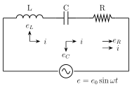
Drawn by us to help you understand the concept clearly, and verified to make sure it's accurate. For exams, practice from your textbook's own diagram.
What this figure shows. The same series LCR circuit diagram as Fig. 13.12 -- resistor R, inductor L and capacitor C in series, common current i, connected across an AC source of emf -- redrawn here specifically to accompany the derivation of the AVERAGE POWER dissipated when a phase difference exists between the applied emf and the resulting current , i.e. it is the identical physical circuit as Fig. 13.12 but the accompanying text now works with the general phase-shifted current expression ra …
Worked out. A sinusoidal voltage of peak V and frequency Hz is applied to a series LCR circuit with , H and F. First, and . The impedance is . The phase angle follows from , giving (current LAGS voltage, since , an inductance-dominated circuit). The power factor is . Finally the power dissipated is W. This example chains together every quantity developed in sections 13.5.4 and 13.6.4 -- reactances, impe …