Question 43 of 50
Q.Derive an expression for the impedance of an LCR circuit connected to an AC power supply. Draw phasor diagram.
Maharashtra MsbshseMaharashtra HSC (MSBSHSE) Board 2024Subjective· 3mImportance★★★★★
86% · 43/50 Questions
You're viewing a preview — the full solution, concept, methods & PYQ mapping are locked.
Start your 14-day free trial to unlock the full solution →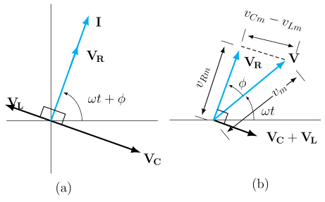
Impedance of a series LCR circuit derived from the phasor diagram.
In a series LCR circuit carrying current (common to all elements, taken as reference phasor along the x-axis):
- Voltage across R, , is in phase with .
- Voltage across L, , leads by .
- Voltage across C, , lags by .
Since and are exactly opposite in phase (both perpendicular to but in opposite senses), their resultant is , still perpendicular to . By the phasor (vector) diagram, the applied voltage is the resultant of the perpendicular phasors and :
…
Unlock everything free for 14 days
- Full step-by-step solutions
- Concept-first explanations
- Methods, shortcuts & mistakes
- PYQ mapping + timed mock tests
Full access for 14 days. No credit card required.