Physics · Ch 16 — Semiconductor Devices
Filter Circuits
Filter Circuits
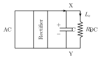
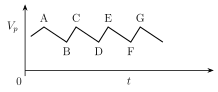
A rectifier's raw output -- whether half wave or full wave -- is unidirectional but still far from steady: it keeps fluctuating because of the ripple component present in it. A FILTER CIRCUIT is the block placed right after the rectifier specifically to remove this AC ripple component (or as much of it as possible) and pass through mainly the DC component, so that the load sees a much steadier voltage than the raw rectified output. The simplest and most widely used filter is the CAPACITOR filter: a capacitor C is connected in PARALLEL with the load resistor , directly across the rectifier's pulsating output. As the rectified voltage rises during each pulse, the capacitor charges up, reaching the peak rectified voltage at the end of a quarter cycle. Once the rectified voltage begins to fall again (as the diode's conduction pulse ends), the capacitor cannot discharge instantly -- it discharges only gradually through , so the voltage across the load drops only slightly, down to a point B, before the NEXT rectified pulse arrives and recharges the capacitor straight back up to . Repeating every cycle, this charge-discharge action smooths the sharply pulsating rectified waveform into a much gentler, nearly-flat output with only a small residual ripple (Fig. 16.6c) -- still technically an UNREGULATED DC supply (its output level still shifts somewhat if the load current changes), but a large practical improvement over the raw rectifier output. The capacitor filter's low cost, small size, and light weight make it especially popular for small-load-current applications such as battery eliminators. A power supply whose output voltage changes noticeably w …
Drawn by us to help you understand the concept clearly, and verified to make sure it's accurate. For exams, practice from your textbook's own diagram.
What this figure shows. The pulsating DC output of a rectifier (drawn simply as a two-terminal source feeding into this stage) is connected across a CAPACITOR C, which in turn is connected in PARALLEL with the load resistor -- i.e. the capacitor and sit side by side, both directly across the rectifier's output terminals, so the same voltage appears across both. This parallel capacitor is the filtering element: it charges up as the rectified voltage rises and discharges through as the rectified voltage falls, smoothing out …
Drawn by us to help you understand the concept clearly, and verified to make sure it's accurate. For exams, practice from your textbook's own diagram.
What this figure shows. A time-axis graph of the voltage across once the capacitor filter is in place. The curve rises steeply to a peak value labelled (the capacitor charging up to the peak of each rectified pulse), then instead of dropping sharply back towards zero (as the unfiltered pulsating output would), it decreases only GRADUALLY and gently -- a slow, near-linear or slightly-curved downward slope -- down to a lower point labelled B, because the capacitor is discharging slowly through rather than the source voltage itself falling to zero. Before the voltage across can drop much further, the NEXT rectified pulse arrives and recharges the capacitor back up to , so the whole waveform is a repeating saw-tooth-like pattern of a sharp rise to followed by a shallow decline to point B, sitting well above the time axis throughout -- unlike the fully-pulsating (undischarged …