Physics · Ch 16 — Semiconductor Devices
Full Wave Rectifier
Full Wave Rectifier
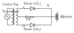
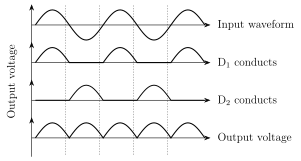
The half wave rectifier's fundamental weakness is that it throws away every negative half cycle of the input entirely, so its efficiency is very poor. A full wave rectifier fixes this by using TWO diodes, and , conducting alternately, so that current flows through the load resistor in the SAME direction during both halves of the input cycle -- nothing is wasted. The standard full wave circuit uses a CENTRE-TAPPED transformer: its secondary winding has two end terminals A and B plus a centre-tap point. is connected so it conducts during the positive half cycle (when A is at higher potential), sending current along the path A-P-Q-R-C through the load; is connected so it conducts during the negative half cycle (when B is at higher potential), sending current along the path B-P-Q-R-C -- through the SAME load, in the SAME direction, just via the other diode. The result (Fig. 16.5) is that every half cycle of the AC input -- positive or negative -- contributes one pulse to the output, so the output consists of a continuous, unbroken train of positive pulses with no gaps at all, unlike the half wave rectifier's alternating pulse-then-gap pattern. Two direct consequences follow, both worked out in Example 16.1: since TWO output pulses now occur per input cycle (one from each diode) instead of one, the output (and ripple) frequency of a full wave rectifier is DOUBLE the input frequency (e.g. 100 Hz output for a 50 Hz mains input, ve …
Drawn by us to help you understand the concept clearly, and verified to make sure it's accurate. For exams, practice from your textbook's own diagram.
What this figure shows. A CENTRE-TAPPED transformer secondary is drawn as a coil with three connection points: end A (top), end B (bottom), and a centre-tap point P exactly midway between them. From end A, a wire runs to the anode of diode ; from end B, a wire runs to the anode of diode . The cathodes of both and are joined together at a common node Q, from which a wire runs down through the load resistor to a node R, which connects back to the centre-tap P, closing the circuit (forming the loop P-R--Q for the load path, with A--Q and B--Q as the two alternate input paths). During the positive half-cycle (A at higher potential than P), current flows along path A-P-Q-R-C i.e. through ; during the negative half-cycle (B at higher potential than P), current flows along path B-P-Q-R-C i.e. through -- in bot …
Drawn by us to help you understand the concept clearly, and verified to make sure it's accurate. For exams, practice from your textbook's own diagram.
What this figure shows. A stack of FOUR time-axis graphs sharing the same horizontal time scale. Graph 1 (topmost): the full AC input voltage, a complete symmetric sine wave with alternating positive and negative half-cycles. Graph 2: the current contributed by diode alone -- positive humps exactly matching the input's positive half-cycles, and exactly zero (flat at the axis) during the input's negative half-cycles. Graph 3: the current contributed by diode alone -- the mirror pattern, zero during the input's positive half-cycles, and a positive hump (of the same shape/amplitude as graph 2's humps) during each of the input's negative half-cycles. Graph 4 (bottommost): the TOTAL combined output across , obtained by adding graphs 2 and 3 -- a continuous, unbroken sequence of positive humps with NO flat zero gaps between them at all (unlike the half-wave cas …
Worked out. The worked example asks: if a 50 Hz AC input is applied to (a) a half wave rectifier and (b) a full wave rectifier, what is the output frequency in each case? For (a) the half wave rectifier produces exactly ONE pulse of DC output for every one full cycle of the AC input (only the positive half-cycles conduct), so the output frequency equals the input frequency: 50 Hz. For (b) the full wave rectifier produces TWO pulses of DC output for every one full cycle of the AC input (since both and each contribute one pulse per cycle, and they interleave), so the output frequency is double the input frequency: 100 Hz. This same doubling is why a full wave rectifier's ripple is easier to filter than a half wave rectifier's -- the ripple repeats twi …