Physics · Ch 16 — Semiconductor Devices
Half Wave Rectifier
Half Wave Rectifier
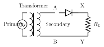
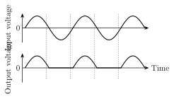
The half wave rectifier is the simplest possible rectifier circuit, built from a single diode. A transformer's secondary coil (with its two ends labelled A and B) is connected in series with a diode D and a load resistor , forming one complete loop. Using a transformer here serves two purposes: it lets the circuit step the incoming AC voltage up or down to whatever level the load needs, and it electrically isolates the rectifier circuit from the mains supply, reducing the risk of shock. As the AC voltage across the secondary coil AB varies sinusoidally, its polarity reverses every half cycle. During the positive half cycle, when point A is at a higher potential than point B, the diode D is forward biased -- it conducts, behaving as a closed switch, and current flows around the loop through . During the negative half cycle, when A is at a lower potential than B, the diode is reverse biased -- it does not conduct, behaving as an open switch, and no current flows. So the diode conducts only during alternate (positive) half cycles and blocks the intervening (negative) half cycles entirely; current always flows through in the same direction, but only in alternating pulses, never continuously. The resulting DC output voltage across therefore takes the form of a series of separated positive pulses (see Fig. 16.3), with a complete gap -- zero output -- during every negative half cycle of the input. Because half of every input cyc …
Drawn by us to help you understand the concept clearly, and verified to make sure it's accurate. For exams, practice from your textbook's own diagram.
What this figure shows. A transformer is shown with its primary winding connected to the AC mains supply, and its secondary winding drawn as a coil with its two ends labelled A (top) and B (bottom). From terminal A, a wire runs to the anode of a single diode D (drawn as a triangle pointing towards a bar, the standard diode symbol), and the cathode of D connects onward to the top of a load resistor . The bottom of connects back to terminal B of the secondary winding, completing the series loop: secondary coil -- diode D -- load -- back to secondary coil. The output DC voltage is taken across . The diode's orientation is drawn so that when A is at higher potential than B ( …
Drawn by us to help you understand the concept clearly, and verified to make sure it's accurate. For exams, practice from your textbook's own diagram.
What this figure shows. Two stacked time-axis graphs, one above the other, sharing the same horizontal time scale. The TOP graph shows the AC input voltage across the secondary coil AB: a full, symmetric sine wave with equal positive and negative half-cycles, oscillating smoothly above and below the zero line, repeating periodically. The BOTTOM graph shows the corresponding output voltage across : it is IDENTICAL in shape to the positive half-cycles of the input sine wave for the duration each positive half-cycle lasts (same hump shape, same amplitude, same timing), but is exactly ZERO (a flat line coinciding with the time axis) for the entire duration of every negative half-cycle of the input -- so the output consists only of alternating positive humps separated b …