Physics · Ch 16 — Semiconductor Devices
Light Emitting Diode / LED
Light Emitting Diode / LED
The LIGHT EMITTING DIODE (LED) is a diode that emits light when a sufficiently large forward current is passed through it. Its construction differs from an ordinary rectifier diode: the n-region is doped more heavily than the p-region, and the p-n junction is encased inside a dome-shaped transparent case, which lets light escape uniformly in all directions while minimising internal reflections that would otherwise trap and waste light within the device. Metal electrodes attached to either side of the junction serve as the external electrical contacts; by convention, the longer of an LED's two legs is its positive terminal, the anode. LEDs with more than the usual two pins (3, 4, or 6-pin packages) are also available, allowing multiple colours to be produced from a single LED package, and surface-mounted LED displays are common for mounting directly onto PCBs.\n\nWorking (Fig. 16.16): when the LED is forward biased, electrons from the semiconductor's conduction band recombine with holes in the valence band near the junction, and each such recombination event releases its excess energy as a PHOTON -- since this energy corresponds to a well-defined value (approximately the material's band gap), the emitted light is essentially MONOCHROMATIC (a single colour). Because the junction region is very thin, a substantial fraction of these photons can escape the device rather than being reabsorbed, and the LED is fabricated so that recombination happens preferentially at the surface, maximising light output; the amount of light emitted is directly proportional to the forward current -- more current, more light. The LED's I-V characteristic (Fig. 16.17) resembles an ordinary forward diode's, but with a noticeably HIGHER cut-in (turn-on) voltage, typically in the range 1.5 to 3.5 V (versus roughly 0.6-0.7 V for silicon diodes); because the LED's current rating is only a few tens of milliamps, a suitably high series resistance must always be connected with it to limit current.\n\nThe wavelength (and hence colour) of light an LED emits is set by the semiconductor material used and, more precisely, by its band gap -- by varying the elements and their proportions in a compound semiconductor, different colours can be produced: aluminium gallium arsenide (AlGaAs) emits infrared radiation; gallium arsenic phosphide (GaAsP) produces red or yellow light; aluminium gallium phosphide (AlGaP) produces red or green light; and zinc selenide (ZnSe) produces blue light. (A blue LED, which enabled the later development of white-light LEDs via wavelength conversion -- typically exciting a yellow phosphor with blue LED light, whose combined blue-plus-yellow emission appears white -- was itself a landmark invention recognised with a Nobel Prize in Physics.) Advantages of LEDs include being a solid-state light source with no filament, tube, or bulb to break; high energy efficiency (substantial light output per watt of input power); very long operating lifetimes; almost no warm-up delay (light output begins within nanoseconds); excellent, non-fading colour rendering, ideal for …

Drawn by us to help you understand the concept clearly, and verified to make sure it's accurate. For exams, practice from your textbook's own diagram.
What this figure shows. The standard diode symbol -- a solid triangle (anode, A) pointing towards a straight bar (cathode, K) -- with two small arrows drawn pointing OUTWARD and away from the symbol (typically from near the triangle/bar junction, angled up and to the right), the opposite orientation from the photodiode's inward-pointing arrows, representing light being EMITTED by the device ra …
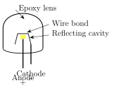
Drawn by us to help you understand the concept clearly, and verified to make sure it's accurate. For exams, practice from your textbook's own diagram.
What this figure shows. A packaged LED's internal cross-section: at the base, a metal reflecting cavity (a small cup-shaped reflector) holds the semiconductor die where the p-n junction sits, with the cathode (-) lead connected directly to/near this reflecting cavity at the base and the anode (+) lead connected via a thin wire bond running up from the die to a separate lead. The whole assembly -- die, reflecting cavity, and wire bond -- is encased within a dome-shaped clear EPOXY LENS moulded over the top, which both protects the junction and optically shapes/focuses the emitted light upward and outward through the dome, minimising internal …
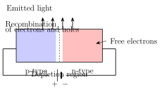
Drawn by us to help you understand the concept clearly, and verified to make sure it's accurate. For exams, practice from your textbook's own diagram.
What this figure shows. A simplified energy-band-style diagram at the forward-biased p-n junction, showing electrons in the CONDUCTION band (on the n-side/near the junction) moving across into the junction region and recombining there with holes present in the VALENCE band (on the p-side), each individual recombination event releasing energy equal to (approximately) the band gap in the form of an emitted PHOTON (drawn as a small wavy arrow or light-ray symbol leaving the recombination site), illustrating that it is this electron-hole recombination -- not heating, not reverse breakdown -- that is the direct source of the light output, with the photon's ener …
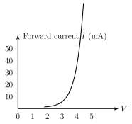
Drawn by us to help you understand the concept clearly, and verified to make sure it's accurate. For exams, practice from your textbook's own diagram.
What this figure shows. A current-vs-voltage graph for an LED, similar in overall shape to an ordinary forward-biased diode's characteristic: negligible current for small forward voltages, then a CUT-IN voltage is reached (marked on the horizontal axis, and noted elsewhere in the chapter to be considerably higher for an LED than for an ordinary diode -- typically in the 1.5 to 3.5 V range rather than the usual 0.6-0.7 V) beyond which the current rises steeply with further increase in forward voltage, the curve bending upward sharply past the cut-in point exactly as a standard forward diode charac …