Physics · Ch 7 — Wave Optics
Fraunhofer Diffraction at a Single Slit
Fraunhofer Diffraction at a Single Slit
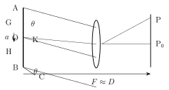
Consider a single slit of width a, with its width lying in the plane of the page and its (much longer) length running perpendicular to the page, illuminated by a plane wavefront (Fig. 7.15). Conceptually, the slit can be imagined as divided into an enormous number of extremely thin sub-slits (secondary sources), each emitting cylindrical wavelets, per Huygens' principle, the instant the plane wavefront reaches it; a cylindrical lens placed just beyond the slit converges these emerging beams onto a screen at its focal plane (distance D from the slit, effectively the lens's focal length F, since for all practical slit widths of to m against a typical D of order 10 m).
Drawn by us to help you understand the concept clearly, and verified to make sure it's accurate. For exams, practice from your textbook's own diagram.
What this figure shows. Plane wavefront on a single slit AB of width a. Rays diffracted at angle θ have a path difference BC = a sin θ between the extreme rays. When this equals nλ the slit splits into pairs that cancel, giving a minimum; the central maximum (at P0) i …
All the rays travelling parallel to the original (undeviated) axis, from every point across the slit from edge A to edge B, converge to the same CENTRAL point directly opposite the slit's midpoint O; since these rays are all parallel and therefore have equal optical path lengths to , they arrive exactly in phase, producing the brightest possible CONSTRUCTIVE interference right at the centre.
Now consider a point P on the screen at angular position from the axis. Drawing a construction line AC from the top edge A, perpendicular to the direction of the rays heading towards P (so AC is normal to the direction ), the segment represents the PATH DIFFERENCE between the two extreme rays from the slit's edges A and B reaching angle : . Suppose this path difference equals exactly one full wavelength, . Bisecting AC at its midpoint K conceptually splits the slit into two equal halves -- from A to the slit's centre O, and from O to B -- and any pair of points equally spaced from A and from O respectively (such as G above O and H below O, symmetric about O) then has a path difference of exactly at point P, producing DESTRUCTIVE interference for that pair. Since this pairing exhausts the ENTIRE slit (every point in the upper half has a matching partner in the lower half, all with path difference ), the light from the whole slit cancels out completely at P -- making P the location of the FIRST diffraction MINIMUM. The identical argument, extended to path differences of between the extreme rays, locates every successive minimum; the same reasoning applies symmetrically on the other side of the central maximum too. In general, the nth minimum occurs where (), and the (approximate, not exact) maxima fall roughly midway between successive minima, near .
Since makes a small angle, (y being the distance of the point on the screen from the centre), so the DISTANCES of the nth dark and (approximate) nth bright points from the centre work out to and . The spacing between consecutive minima (or, equivalently, between consecutive maxima away from the centre) is -- a formula that looks exactly like Young's double-slit fringe width, but with the slit WIDTH a in place of the slit SEPARATION d, and with one crucial exception: the CENTRAL bright fringe -- spanning between the first minimum on either side, at -- is TWICE as wide, , as every other bright fringe in the pattern. …
Physical quantity | Young's double slit interference pattern | Single slit diffraction pattern
Fringe width, W | | (except the central bright fringe, which is twice as wide)
Phase difference (extreme rays) at nth bright fringe | |
Angular position, θ, of nth bright fringe | |
Path difference (extreme rays) at nth bright fringe | |
Distance from central bright spot, y, of nth bright fringe | |
Phase difference (extreme rays) at nth dark fringe | |
Angular position, θ, of nth dark fringe | |
Path difference (extreme rays) at nth dark fringe | | …