Physics · Ch 7 — Wave Optics
Resolving Power of a Microscope
Resolving Power of a Microscope
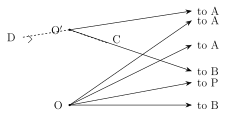
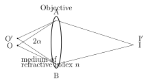
For a microscope viewing two nearby POINT objects O and O', separated by a small distance a, immersed in a medium of refractive index n, with the objective lens AB subtending a half-angle at the objects (full angular aperture ) and the light's wavelength in that medium being (Fig. 7.19(a)): the two objects' Airy diffraction patterns, formed effectively at infinity (on the eyepiece or a screen), have their central maxima at points I and I' respectively. Applying Rayleigh's criterion, the first dark ring of O''s pattern should coincide with I (O's central maximum), and vice versa.
Drawn by us to help you understand the concept clearly, and verified to make sure it's accurate. For exams, practice from your textbook's own diagram.
What this figure shows. An enlargement of the region around O and O' showing the geometry. The path difference between the extreme rays to the first dark ring is DO' + O'C = 2a sin α; setting this equal to the resolving condition gives the smallest …
Drawn by us to help you understand the concept clearly, and verified to make sure it's accurate. For exams, practice from your textbook's own diagram.
What this figure shows. Two point objects O and O' a distance a apart sit in front of a microscope objective AB (medium of refractive index n). They subtend an angle 2α at the objective. Their Airy patterns on the screen are just resolved when the first dark ring o …
Working out the geometry (Fig. 7.19(b)) for the point I where O''s first dark ring is located: since I is equidistant from the two edges A and B of the objective, the extreme ray paths -to-I and -to-I differ in length only over the segment near O', and this PATH DIFFERENCE works out, by straightforward trigonometry on the small triangle near O and O', to .
Two distinct cases then apply, differing only in the numerical constant used for the path difference AT the first dark ring itself:
- Non-luminous (externally illuminated) point objects -- the usual case in ordinary microscopy, where objects do not emit their own light but are lit by some external source, often through an eyepiece medium of refractive index n, so the relevant wavelength there is : the path difference at the first dark ring works out, in this illuminated case, to simply itself, giving , i.e. , where is called the NUMERICAL APERTURE (N.A.) of the objective -- and correspondingly the resolving power is .
- Self-luminous point objects -- applying Abbe's fuller theory of Airy-disc diffraction directly to Fraunhofer diffraction, the path difference at the true first dark ring works out instead to , giving , i.e. , with resolving power . …