Physics · Ch 7 — Wave Optics
Young's Double Slit Experiment
Young's Double Slit Experiment
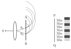
In Young's double slit experiment, a plane wavefront is made to fall on an opaque screen AB pierced by two narrow, IDENTICAL, closely-spaced (typically 2-4 mm apart) parallel slits, and , with their lengths running perpendicular to the plane of the diagram (Fig. 7.10). The plane wavefront itself is obtained either by placing a linear source S far away from the slit screen, or (more compactly) by placing S at the focus of a converging lens positioned just before AB. A second, observing screen PQ is placed some distance behind AB; for simplicity, and are taken to be equidistant from S, so the wavefronts reaching them from S are always in phase with each other.
Drawn by us to help you understand the concept clearly, and verified to make sure it's accurate. For exams, practice from your textbook's own diagram.
What this figure shows. A plane wavefront reaches two narrow slits S1 and S2 (on screen AB), which act as coherent secondary sources emitting cylindrical wavelets. The wavelets superpose on the screen PQ: constructive interference gives bright fringes (Max), destructive gives dark fringes (Min), …
When the incident plane wavefront reaches and , both slits act as coherent secondary sources (per Huygens' principle), each emitting cylindrical wavelets into the region to the right of AB -- coherent because both are driven, always in phase with each other, by the same single original wavefront. Where the crests (or troughs) of these two wavelet trains overlap, constructive interference produces BRIGHT regions on the screen; midway between these, where a crest from one source meets a trough from the other, destructive interference produces DARK regions. The alternating bright and dark bands together are called FRINGES, and the whole pattern the INTERFERENCE PATTERN.
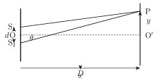
To locate the fringes mathematically (Fig. 7.11), set up x-y axes with x along the original propagation direction and the observing screen along the y-z plane (y in the plane of the page); let O be the midpoint of (separation d), and O' the corresponding point directly opposite O on the screen, at distance D from the slit plane (with , needed for the small-angle approximations that follow). Since O' is equidistant from and , the two wavelet trains reach it with zero path difference -- always in phase, giving a BRIGHT fringe exactly at the centre O' of the screen (the CENTRAL fringe).
Drawn by us to help you understand the concept clearly, and verified to make sure it's accurate. For exams, practice from your textbook's own diagram.
What this figure shows. The geometry used to locate the fringes: the slits S1 and S2 are a distance d apart, the screen is a distance D away, and P is a point at height y above the central point O'. The path difference S2P − S1P = yd/D determines whether P is bright ( …
For a general point P on the screen at height y above O', the two wavelets from and travel different distances, and . Using , and factoring the left side as , together with the approximation (valid since ), gives the PATH DIFFERENCE directly: .
Constructive interference (a BRIGHT fringe) occurs wherever this path difference equals a whole number of wavelengths: (), giving the position of the nth bright fringe as . Destructive interference (a DARK fringe) occurs wherever the path difference is a HALF-integer multiple of : , giving . The spacing between any two consecutive bright fringes (or, equally, between any two consecutive dark fringes) turns out to be exactly the same everywhere -- this constant spacing is called the FRINGE WIDTH, : bright and dark fringes are both equally spaced and equally wide across the whole pattern. …