Q.Draw the circuit diagram of a summing amplifier using an operational amplifier.
You're viewing a preview — the full solution, concept, methods & PYQ mapping are locked.
Start your 14-day free trial to unlock the full solution →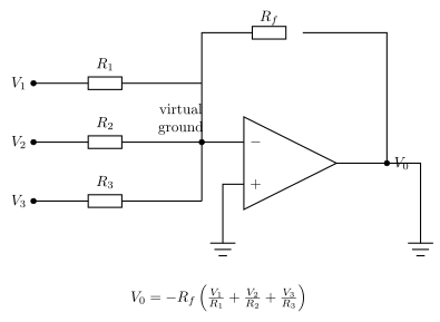
A summing amplifier is an inverting op-amp circuit with several input resistors feeding a common virtual-ground (inverting) node and one feedback resistor, giving an output equal to the negative weighted sum of the inputs.
Circuit description (as printed in the paper)
The circuit uses an operational amplifier (op-amp) connected in the inverting configuration, extended to accept several inputs simultaneously:
- Three (in general, ) input voltages are each applied through their own separate input resistors , and all three resistors are joined at a single common node, which is connected to the inverting () input terminal of the op-amp.
- The non-inverting () input terminal of the op-amp is connected directly to ground (0 V).
- A single feedback resistor connects the output terminal of the op-amp back to the same inverting-input node.
- The output voltage is taken between the op-amp's output pin and ground.
How it works (derivation of the output relation)
Because the op-amp has very high open-loop gain, in a stable feedback configuration the inverting input is held at a virtual ground (0 V), and no current flows into the op-amp's input terminals. Applying Kirchhoff's current law at the inverting-input node, the sum of the currents flowing in through must equal the current flowing out through into the output: …
Unlock everything free for 14 days
- Full step-by-step solutions
- Concept-first explanations
- Methods, shortcuts & mistakes
- PYQ mapping + timed mock tests
Full access for 14 days. No credit card required.