Question 61 of 88
Q.Draw the circuit diagram of OR-gate using diodes.
Puducherry TnboardTamil Nadu HSC (DGE) Board 2018Subjective· 3mImportance★★★★★
69% · 61/88 Questions
You're viewing a preview — the full solution, concept, methods & PYQ mapping are locked.
Start your 14-day free trial to unlock the full solution →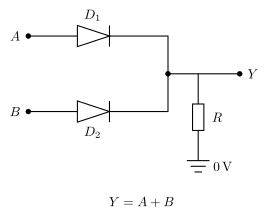
A two-input diode OR gate uses diodes and with their anodes connected to inputs and and their cathodes joined at a common output, so the output goes HIGH whenever either input is HIGH.
- Circuit description (diagram described in words): input is connected through diode (anode at , cathode at the output node) and input through diode (anode at , cathode at the same output node) to a common output terminal . A resistor connects to ground/the reference (0 V) level. …
Unlock everything free for 14 days
- Full step-by-step solutions
- Concept-first explanations
- Methods, shortcuts & mistakes
- PYQ mapping + timed mock tests
Full access for 14 days. No credit card required.