Why a PN Junction Biases the Way It Does
A PN junction is not a resistor. Its current-voltage behaviour is fundamentally asymmetric — and that asymmetry comes directly from the physics of the depletion region and the energy barrier it creates.
The Unbiased Junction: A Built-in Barrier
When P-type and N-type semiconductors are joined, holes from the P-side diffuse into the N-side, and electrons from the N-side diffuse into the P-side. This diffusion leaves behind fixed, charged ions: negative acceptor ions on the P-side, positive donor ions on the N-side. These ions create an electric field that opposes further diffusion.
The result is a depletion region — a zone with no free carriers — and a built-in potential V0 across it. This potential acts as an energy barrier that prevents net current flow at equilibrium.
At equilibrium (zero bias), the net current is zero. The diffusion current (due to concentration gradient) is exactly balanced by the drift current (due to the built-in electric field).
Forward Bias: Lowering the Barrier
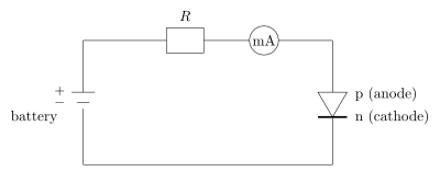
Apply a positive voltage V to the P-side relative to the N-side. This external voltage opposes the built-in potential. The net barrier becomes:
Vnet=V0−V
The depletion width shrinks. More importantly, the energy barrier for majority carriers (holes from P-side, electrons from N-side) is reduced. A larger number of carriers now have enough energy to cross the junction.
The current that flows is diffusion current — carriers injected across the junction become minority carriers on the other side, where they recombine. The relationship is exponential because the number of carriers with energy above the barrier follows a Boltzmann distribution.
I=I0(eqV/kT−1)
Here I0 is the reverse saturation current (very small), q is the electron charge, k is Boltzmann's constant, and T is absolute temperature.
Why the exponential? The fraction of carriers with enough energy to surmount a barrier of height q(V0−V) is proportional to e−q(V0−V)/kT. At equilibrium (V=0), this gives a current that exactly cancels the drift current. When V>0, the barrier drops, and the net current becomes proportional to eqV/kT.
Reverse Bias: Raising the Barrier
Apply a negative voltage to the P-side relative to the N-side. Now the external voltage adds to the built-in potential:
Vnet=V0+VR
The barrier becomes higher. The depletion region widens. Diffusion of majority carriers is almost completely suppressed. The only current that flows is a tiny reverse saturation current I0, carried by minority carriers (electrons from the P-side, holes from the N-side) that are swept across by the electric field.
This current is essentially constant with voltage because the number of minority carriers is fixed by thermal generation — it does not depend on the barrier height once the barrier is large enough to block majority carriers. …