Q.Describe the experimental set up for obtaining output characteristic curve of a PNP transistor in common emitter configuration with suitable circuit diagram. Also draw the curve obtained. Select possible value of common base current amplification factor alpha of a transistor among the following. 0.9, 9, 19, 49 and 99.
You're viewing a preview — the full solution, concept, methods & PYQ mapping are locked.
Start your 14-day free trial to unlock the full solution →Fix I_B, vary V_CE, measure I_C to get output characteristics (I_C vs V_CE for several I_B); because alpha is always less than 1, the only possible value listed is 0.9.
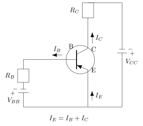
Experimental set-up (common-emitter, PNP):
Circuit (described): The emitter is common to input and output. A battery V_BB with a rheostat and a microammeter drives the base-emitter (input) loop through a resistor; a milliammeter and battery V_CC with a rheostat form the collector-emitter (output) loop. For PNP, the emitter is at higher potential (emitter-base forward biased, collector-base reverse biased); polarities are reversed relative to NPN. Meters: microammeter for I_B, voltmeter for V_CE, milliammeter for I_C.
Procedure for output characteristics:
- Keep the base current I_B fixed at a chosen value (say 10 microampere).
- Vary the collector-emitter voltage V_CE in steps and note the collector current I_C at each step.
- Plot I_C (y-axis) versus V_CE (x-axis) for that I_B.
- Repeat for higher fixed I_B values to get a family of curves. …
Unlock everything free for 14 days
- Full step-by-step solutions
- Concept-first explanations
- Methods, shortcuts & mistakes
- PYQ mapping + timed mock tests
Full access for 14 days. No credit card required.