Q.A source of alternating e.m.f. is connected to a series combination of a resistor R, an inductor L, and a capacitor C. Obtain with the help of a vector diagram and impedance diagram, an expression for
You're viewing a preview — the full solution, concept, methods & PYQ mapping are locked.
Start your 14-day free trial to unlock the full solution →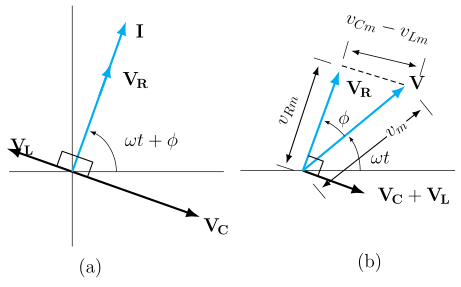
Representing the voltages across , , and as phasors relative to the common current and combining them vectorially gives the effective applied voltage, the impedance of the series RLC circuit, and the phase angle between current and voltage.
Setup
A resistor , inductor , and capacitor are connected in series across a source of alternating emf . Since they are in series, the same instantaneous current flows through all three elements at every instant. Let , , be the voltage amplitudes across , , respectively.
Phase of each voltage relative to the current
- The voltage across the resistor, , is in phase with the current .
- The voltage across the inductor, (where is the inductive reactance), leads the current by .
- The voltage across the capacitor, (where is the capacitive reactance), lags the current by .
Vector (phasor) diagram
Take the current as the reference phasor along the horizontal axis. is drawn along this same direction. is drawn perpendicular to , rotated ahead (anticlockwise). is drawn perpendicular to , rotated behind (clockwise) — i.e. in the direction exactly opposite to . Since and are antiparallel ( apart), they combine into a single net reactive phasor of magnitude along the direction of (assuming ; if the net reactive phasor points the other way).
The resultant applied voltage is the vector sum of (along the current) and (perpendicular to the current) — these two are mutually perpendicular, so by the parallelogram/Pythagorean rule:
(i) Effective (applied) voltage
Substituting , , :
(ii) Impedance
…
Unlock everything free for 14 days
- Full step-by-step solutions
- Concept-first explanations
- Methods, shortcuts & mistakes
- PYQ mapping + timed mock tests
Full access for 14 days. No credit card required.