Skip to content
Question
Figure — Figure — 55/6/1 Q29
FigureFigure — 55/6/1 Q29

Q.Case study (Capacitors): A capacitor is a system of two conductors separated by an insulator, with charges QQ and −Q-Q and potential difference VV; the ratio Q/V=CQ/V = C is the capacitance, depending only on geometry and the medium. Inserting a dielectric polarises it, changing the field, capacitance and stored energy. Capacitors can be arranged in series/parallel.

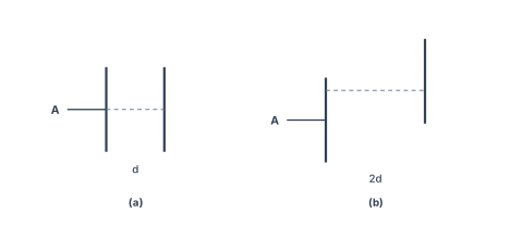
(i) A capacitor of capacitance C, plate area A and separation d, is filled with air [Fig.(a)]. The separation is increased to 2d and one plate is shifted as shown in Fig.(b). The capacitance of the new system is: (A) C4\dfrac{C}{4} (B) C2\dfrac{C}{2} (C) 2C2C (D) 4C4C
(ii) A slab (area A, thickness d1d_1) of a linear dielectric of dielectric constant K is inserted between charged plates (charge density σ\sigma) of a parallel plate capacitor; opposite charges of density σp\sigma_p appear on the slab faces. The dielectric constant K is given by: (A) σ+σpσ\dfrac{\sigma+\sigma_p}{\sigma} (B) σσ−σp\dfrac{\sigma}{\sigma-\sigma_p} (C) σ+σpσp\dfrac{\sigma+\sigma_p}{\sigma_p} (D) σσp\dfrac{\sigma}{\sigma_p}.
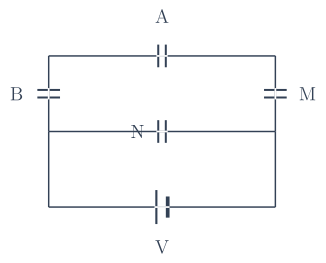
(iii) An electric field E is established between the plates of an air-filled parallel plate capacitor with charges Q and −Q-Q; V is the volume enclosed. The energy stored is: (A) ε0E2\varepsilon_0 E^2 (B) ε0Q2E\varepsilon_0 Q^2 E (C) 12ε0E2V\frac{1}{2}\varepsilon_0 E^2 V (D) ε0EQV\varepsilon_0 E Q V. (iv)(a) Three capacitors A, B and M, each of capacitance C, are connected to a capacitor N of capacitance 2C and a battery as shown in the figure. If the charges on A and N are QAQ_A and QNQ_N respectively, then QN/QAQ_N/Q_A is: (A) 16\dfrac{1}{6} (B) 13\dfrac{1}{3} (C) 3 (D) 6.
(OR)
(iv)(b) A slab (area A and thickness d/2) of dielectric constant K is inserted in a parallel plate capacitor of plate area A and plate separation d. If C and C0C_0 are the capacitances with and without the dielectric, then C/C0C/C_0 is: (A) K+12K\dfrac{K+1}{2K} (B) 2KK+1\dfrac{2K}{K+1} (C) KK−1\dfrac{K}{K-1} (D) K−1K\dfrac{K-1}{K}.
CBSECBSE Class XII Board 2025Subjective· 4mImportance★★★★★
🔒 Locked · start free trial →

You're viewing a preview — the full solution, concept, methods & PYQ mapping are locked.

Start your 14-day free trial to unlock the full solution →

(i) C→C/4C\to C/4; (ii) K=σσ−σpK=\frac{\sigma}{\sigma-\sigma_p}; (iii) U=12ε0E2VU=\frac12\varepsilon_0E^2V; (iv)(a) QN/QA=6Q_N/Q_A=6 (bridge network -- N sits directly across the battery, P1/P2 are floating nodes); (iv)(b) C/C0=2KK+1C/C_0=\frac{2K}{K+1}.

Part (a)

Figure — 55/6/1 Q29
Figure — 55/6/1 Q29

(i) Change of geometry

For a parallel-plate capacitor C=ε0AdC=\frac{\varepsilon_0A}{d}. Doubling the separation to 2d2d and halving the overlapping area to A/2A/2:

C′=ε0(A/2)2d=14⋅ε0Ad=C4(A).C'=\frac{\varepsilon_0(A/2)}{2d}=\frac14\cdot\frac{\varepsilon_0A}{d}=\frac{C}{4}\quad\text{(A)}.

(ii) Dielectric constant from charge densities

The free-charge field is E0=σε0E_0=\frac{\sigma}{\varepsilon_0}. Induced polarisation charges σp\sigma_p oppose it, so the net field inside is E=σ−σpε0E=\frac{\sigma-\sigma_p}{\varepsilon_0}. By definition

K=E0E=σ/ε0(σ−σp)/ε0=σσ−σp(B).K=\frac{E_0}{E}=\frac{\sigma/\varepsilon_0}{(\sigma-\sigma_p)/\varepsilon_0}=\frac{\sigma}{\sigma-\sigma_p}\quad\text{(B)}.

(iii) Energy in terms of field and volume

U=12CV2=12ε0Ad(Ed)2=12ε0E2(Ad)=12ε0E2V(C),U=\frac12CV^2=\frac12\frac{\varepsilon_0A}{d}(Ed)^2=\frac12\varepsilon_0E^2(Ad)=\frac12\varepsilon_0E^2V\quad\text{(C)},

so the energy density is 12ε0E2\frac12\varepsilon_0E^2.

Figure — 55/6/1 Q29(iv)(a)

(iv)(a) Capacitor network

The stored working here was based on the wrong topology -- once the actual network figure (previously missing) is drawn, it shows a bridge, not a simple series-parallel chain: capacitor A bridges the top rail between nodes P1 and P2; B connects P1 down to P3 (in series on the left); M connects P2 down to P4 (in series on the right); N bridges P3-P4, and the battery is connected directly across the SAME two nodes P3-P4 (in parallel with N).

Because N sits directly across the ideal battery, the potential difference across N is exactly the battery emf VV, regardless of A/B/M:

QN=(2C) V.Q_N=(2C)\,V.

Nodes P1 and P2 are floating (each touches only two capacitors, no direct wire to the battery), so charge conservation applies at each: the charge flowing onto one capacitor's plate at that node must be supplied by the other capacitor at the same node. Taking VP3=VV_{P3}=V, VP4=0V_{P4}=0, and writing V1=VP1V_1=V_{P1}, V2=VP2V_2=V_{P2}:

C(V1−V2)⏟QA (P1 plate)+C(V1−V)⏟QB (P1 plate)=0,−C(V1−V2)⏟QA (P2 plate)+C V2⏟QM (P2 plate)=0.\underbrace{C(V_1-V_2)}_{Q_A\text{ (P1 plate)}}+\underbrace{C(V_1-V)}_{Q_B\text{ (P1 plate)}}=0,\qquad -\underbrace{C(V_1-V_2)}_{Q_A\text{ (P2 plate)}}+\underbrace{C\,V_2}_{Q_M\text{ (P2 plate)}}=0.

Solving this pair: the second equation gives V1=2V2V_1=2V_2; substituting into the first gives V2=2V1−V=4V2−VV_2=2V_1-V=4V_2-V, so V2=V3V_2=\dfrac{V}{3} and V1=2V3V_1=\dfrac{2V}{3}.

The charge on A is then

QA=C(V1−V2)=C(2V3−V3)=CV3.Q_A=C(V_1-V_2)=C\left(\frac{2V}{3}-\frac{V}{3}\right)=\frac{CV}{3}.

So

QNQA=2CVCV/3=6(D).\frac{Q_N}{Q_A}=\frac{2CV}{CV/3}=6\quad\text{(D)}. …

Unlock everything free for 14 days

  • Full step-by-step solutions
  • Concept-first explanations
  • Methods, shortcuts & mistakes
  • PYQ mapping + timed mock tests

Full access for 14 days. No credit card required.