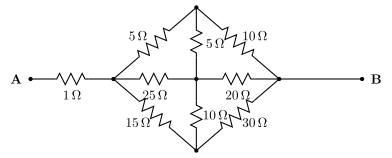
Q.Find the equivalent resistance between points A and B for the network shown in the figure.
You're viewing a preview — the full solution, concept, methods & PYQ mapping are locked.
Start your 14-day free trial to unlock the full solution →The real network (see figure) is a 5-node bridge -- A through a resistor to node P, then P branches into a bridge of nodes T (top), Ctr (centre), and Bot (bottom) before rejoining at node Q, which connects to B by a plain wire. Because node Ctr connects to four different nodes (P, T, Bot, and Q), this network does not reduce by simple series-parallel combination -- it must be solved with Kirchhoff's laws (the node-voltage / junction-rule method). Doing so gives .
Why this needs Kirchhoff's laws, not series-parallel shortcuts
Reading the figure: A connects to P through . From P, three resistors fan out to T (), to Ctr (), and to Bot (). T and Bot each also connect to Ctr ( and respectively) and to Q ( and respectively, the two diagonal resistors). Ctr also connects directly to Q (). Finally Q connects to B by a plain wire (so Q and B are the same node electrically).
No two of these nine resistors share both their end-nodes with each other in a simple loop -- every node except A and B touches at least three resistors -- so there is no legal series or parallel combination anywhere in the T/Ctr/Bot/Q cluster. This is the hallmark of a genuine bridge network, and the textbook-correct tool for it is Kirchhoff's junction rule applied at every internal node (equivalently, the node-voltage method).
Setting up the node equations
Since Q and B are the same node, set (reference) and inject a test current at A. All of passes through the resistor into P, so , and (taking for convenience, since the network beyond P is linear).
Applying at each of the three internal nodes (T, Ctr, Bot), with unknown for now:
Node T:
Node Ctr:
Node Bot:
Solving the first and third equations for and in terms of and , then substituting into the middle equation, gives (with for a unit test voltage there): …
Unlock everything free for 14 days
- Full step-by-step solutions
- Concept-first explanations
- Methods, shortcuts & mistakes
- PYQ mapping + timed mock tests
Full access for 14 days. No credit card required.