Q.(a)(i) Write the principle of working of an ac generator. Draw its labelled diagram and explain its working.
(ii) A resistor of 400 Ω, an inductor of π5 H and a capacitor of π50μF are joined in series across an ac source v=140sin(100πt) V. Find the rms voltages across these three circuit elements. The algebraic sum of these voltages is more than the rms voltage of the source. Explain.
(OR)
(b)(i) Write the principle of working of a transformer. With the help of a labelled diagram, explain the working of a step-up transformer.
(ii) An ideal transformer is designed to convert 50 V into 250 V. It draws 200 W power from an ac source whose instantaneous voltage is given by vi=20sin(100πt) V. Find: (I) rms value of input current; (II) expression for instantaneous output voltage; (III) expression for instantaneous output current.
CBSECBSE Class XII Board 2025Subjective· 5mImportance★★★★★
Part (a)Concept understanding — RMS and Peak Value
Why We Need a New Measure
When you push a DC current through a resistor, the power is constant — P=I2R, and the heating is steady. But an AC current keeps changing direction and magnitude. At one instant it's +I0, a moment later it's zero, then −I0. If you simply averaged the current over time, you'd get zero — because the positive and negative halves cancel. That's useless for telling you how much heat the resistor actually feels.
So we need a single number that captures the effective heating power of an alternating current. That number is the RMS value.
The Intuition: Squaring Fixes the Sign Problem
Heat depends on I2, not on I. Squaring the current makes every instant positive — a negative current squared gives the same heat as a positive one of the same magnitude. So instead of averaging the current (which gives zero), we average the square of the current, then take the square root to get back to a current-like number. That's the root-mean-square: Root of the Mean of the Square.
For a sinusoidal current i(t)=I0sin(ωt), the square is I02sin2(ωt). The average of sin2 over a full cycle is exactly 1/2. So:
mean of i2=I02×21
Then:
Irms=2I02=2I0
Irms=2I0andVrms=2V0
The Physical Meaning
If you take a resistor and pass a sinusoidal current of peak value I0 through it, the average power dissipated is exactly the same as if you passed a steady DC current of I0/2 through it. That's why RMS is called the "equivalent DC" value.
Tip
When you see "230 V AC" on a household outlet, that 230 V is the RMS voltage. The peak voltage is 230×2≈325 V. The wire insulation has to handle 325 V peaks, but the heating effect is the same as 230 V DC.
Peak Value
The peak valueI0 (or V0) is simply the maximum instantaneous value the waveform reaches. For a sine wave, it's the amplitude. The RMS value is always smaller than the peak — by a factor of 2 for a pure sine wave. …
Part (b)Concept understanding — Transformer Principle
Transformer Principle: From Intuition to Precision
Imagine you have a water pipe with a narrow section and a wide section. Water flows through the narrow part fast but with low pressure; through the wide part it flows slow but with high pressure. The total amount of water (flow × pressure) stays the same. A transformer does something similar — but for electricity.
A transformer takes AC power at one voltage and current, and delivers nearly the same power at a different voltage and current. If voltage goes up, current must come down, and vice versa. The total power (voltage × current) is almost unchanged — minus a tiny loss.
The Core Idea: Mutual Induction
Two coils of wire are placed near each other, usually wound around a common iron core. When AC flows through the first coil (the primary), it creates a changing magnetic field. That changing field passes through the second coil (the secondary) and induces a voltage across it. This is mutual induction — a changing current in one coil induces a voltage in a neighbouring coil.
The iron core is crucial: it guides the magnetic field from one coil to the other with very little leakage, making the transfer efficient.
Note
A transformer works only with AC. A steady DC current produces a constant magnetic field, which induces nothing in the secondary coil. Change is essential.
The Precise Statement
For an ideal transformer (no energy losses), the relationship between primary and secondary voltages and currents is:
VpVs=NpNsandIpIs=NsNp
where:
Vp, Vs = primary and secondary voltages
Ip, Is = primary and secondary currents
Np, Ns = number of turns in primary and secondary coils
VpIp=VsIs
Power in equals power out (ideal case).
What This Means
If the secondary has more turns than the primary (Ns>Np), the secondary voltage is higher — this is a step-up transformer. Current in the secondary is correspondingly lower.
If the secondary has fewer turns (Ns<Np), the secondary voltage is lower — a step-down transformer. Current in the secondary is higher.
Watch out
A step-up transformer raises voltage but lowers current. It does not create energy. The product V×I stays constant (ignoring losses). Many beginners think a step-up transformer "amplifies" power — it does not.
Why the Turns Ratio Works
The voltage induced in each turn of a coil is the same (because the same changing magnetic flux links every turn). So the total induced voltage is proportional to the number of turns:
Vp∝Np,Vs∝Ns
Dividing gives the ratio. For current, conservation of power forces the inverse relationship.
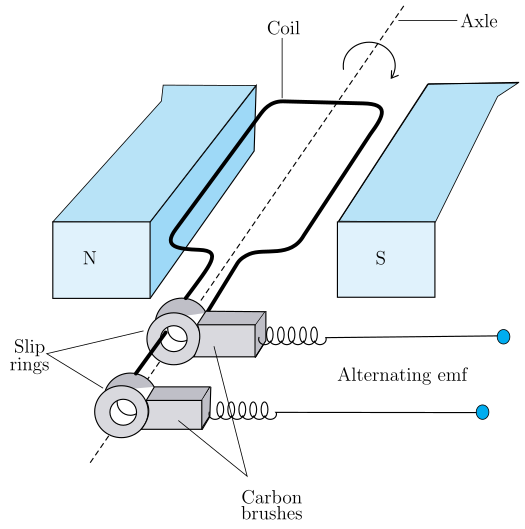
Labelled diagram of an AC generator: a rectangular coil rotates on an axle between the N and S poles of a field magnet; its two ends connect to slip rings that press against fixed carbon brushes, which carry the induced alternating emf out to the external circuit.
Part (a)
AC generator — principle. It works on electromagnetic induction (Faraday's law): when a coil rotates in a uniform magnetic field, the flux through it changes sinusoidally, inducing an alternating emf. A rectangular armature coil (N turns, area A) rotates at angular velocity ω between the poles N–S; slip rings and brushes carry the emf to the load. With Φ=NBAcosωt,
ε=−dtdΦ=NBAωsinωt=ε0sinωt.
Series RLC.R=400Ω,L=π5 H, C=π50μF, v=140sin(100πt) V so ω=100π rad/s, Vrms=2140=702 V.
(a) AC generator converts mechanical to electrical energy by electromagnetic induction; for the RLC circuit VR≈79.2 V, VL≈99 V, VC≈39.6 V, and their algebraic sum exceeds the source because the voltages are out of phase (phasor sum =702≈99 V).
(b) A transformer works on mutual induction; for the given data Ii,rms=102≈14.14 A, vo=100sin(100πt) V, io=4sin(100πt) A.
Labelled diagram of an AC generator: a rectangular coil rotates on an axle between the N and S poles of a field magnet; its two ends connect to slip rings that press against fixed carbon brushes, which carry the induced alternating emf out to the external circuit.
Part (a)
(i) Principle and working of an AC generator
An AC generator rests on Faraday's law of electromagnetic induction: a change of magnetic flux through a coil induces an emf. A rectangular armature coilABCD (N turns, area A) is free to rotate about an axis perpendicular to a uniform field B produced by a field magnet (N–S). Two slip rings fixed to the coil ends rotate with it and press against stationary brushes connected to the external load.
As the coil rotates with angular velocity ω, the flux linked is
Φ(t)=NBAcos(ωt).
By Faraday's law the induced emf is
ε(t)=−dtdΦ=NBAωsin(ωt)=ε0sin(ωt),ε0=NBAω.
The emf reverses every half rotation, so the output current alternates; the slip rings keep continuous contact while allowing free rotation.
(ii) RMS voltages in the series RLC circuit
Given R=400Ω, L=π5 H, C=π50×10−6 F, v=140sin(100πt) V, so ω=100π rad/s and Vrms=2140=702≈98.99 V.
Why the algebraic sum is larger.VR+VL+VC≈79.2+99+39.6=217.8 V, well above Vrms≈99 V. In a series RLC circuit VL leads the current by 90∘ and VC lags by 90∘, so VL and VC are 180∘ apart and partly cancel. The correct combination is the phasor sum
Same / Similar Concept — real previous-year questions on the same or a closely similar concept, not this exact question.
Showing the 12 most recent of 57 on this concept.
CBSE 2026Set A1 markMCQ
Q.The voltage of domestic ac is 220 V. What does this represent?
(A) Peak value voltage
(B) Mean value voltage
(C) Root mean voltage
(D) Root mean square voltage
›Reveal solutionSolution
The 220 V of domestic mains is the RMS (root-mean-square) voltage.
An AC voltage varies sinusoidally, so it is specified by an effective value that produces the same heating as an equivalent DC — the root-mean-square (RMS) value. Household ratings such as "220 V" are RMS values. The peak val …
Q.An ideal transformer has 500 turns in the primary and 5000 turns in the secondary. If the primary be connected to a 6 V battery, then the secondary voltage is
(a) 0
(b) 0.6 V
(c) 60 V
(d) 6 V
›Reveal solutionSolution
A transformer needs a changing current/flux to work. A DC battery gives a constant current, so once steady state is reached the secondary voltage is 0.
A transformer works on the principle of mutual induction: the emf induced in the secondary is
Q.The ratio of root mean square (rms) value and peak value of an alternating current is
(a) 1 : 1
(b) 1 : 2
(c) √2 : 1
(d) 1 : √2
›Reveal solutionSolution
For a sinusoidal alternating current i = i0 sin(omega t), the rms value is i0/root2, so the ratio rms:peak is 1:root2.
RMS (root mean square) value is defined so that it produces the same heating effect as an equivalent DC. For i = i0 sin(omega t), averaging i^2 over a …
Q.The mean value of an alternating current in a half cycle is
(a) I0/sqrt(2)
(b) I0/2
(c) 2*I0/pi
(d) none of these
›Reveal solutionSolution
Averaging I = I0sin(omegat) over one half cycle (0 to pi/omega) gives 2*I0/pi - this is the standard 'mean/average value of AC'.
For a sinusoidal current I = I0sin(omegat), the average over a FULL cycle is zero (positive and negative halves cancel exactly). So the 'mean value' of AC is conventionally defined over just a HALF cycle, where the current keeps one sign throughout. Averaging:
I_mean = (1/T') * integral of I0sin(omegat) dt, over one half period T' = pi/omega
Q.Why cannot a transformer be used to step up direct current (D.C.)?
›Reveal solutionSolution
No changing flux, no induced EMF — a transformer needs AC to work at all.
A transformer operates on the principle of mutual induction: a time-varying current in the primary coil produces a time-varying magnetic flux in the core, which links the secondary coil and induces an EMF in it, given by ε2=−N2dtdΦ. With a constant DC current in the primary, the flux in the core, once established, remains steady (constant) — its rate of change dΦ/dt is zero in the steady state. Since the induced EMF depends entirely on this rate of change, no EMF (and hence no stepped-up voltage) is induced in the secondary for steady DC, so a t …
Q.Statement I : Direct current (DC) is less dangerous than alternating current (AC). Statement II : The rms value of the alternating current (AC) is 70·7% of the peak value.
(a) Only Statement I is true.
(b) Only Statement II is true.
(c) Both Statements I and II are true.
(d) Both Statements I and II are false.
›Reveal solutionSolution
Statement I is true (AC of equal rated voltage is generally more dangerous than DC), and Statement II is true (rms value = peak/√2 = 70·7% of peak). Hence option (c).
Statement I: For the same magnitude, alternating current is generally considered more dangerous than direct current, largely because AC can cause sustained muscular contraction and its effective (rms) value acts continuously. So DC being 'less dangerous' is accepted as true.
Q.An ammeter connected in series in an ac circuit reads 10 A. The maximum value of current at any instant in the circuit is: (A) 102 A (B) 210 A (C) π10 A (D) 2π10 A
›Reveal solutionSolution
An AC ammeter reads the RMS (root-mean-square) value of current. For a sinusoidal AC, the peak (maximum) current is 2 times the RMS value. Given RMS = 10 A, the maximum current is 102 A.
The key here is understanding what an AC ammeter actually measures. Unlike a DC ammeter, which reads the average current, an AC ammeter is calibrated to read the RMS value of the current. For a sinusoidal alternating current, the RMS value is the "effective" value — it tells you the equivalent DC current that would produce the same heating effect in a resistor.
The relationship between the RMS value (Irms) and the peak or maximum value (I0) for a pure sine wave is:
Irms=2I0orI0=Irms×2
This comes from averaging the square of the sine function over one cycle. The factor 2 (approximately 1.414) is a fixed mathematical result for sinusoidal waveforms.
Now let's apply this directly to the problem.
The ammeter reading is given as 10 A. Since it's an AC ammeter, this is the RMS current: Irms=10 A.
We want the maximum instantaneous current, which is the peak value I0. Using the formula above:
I0=Irms×2=10×2 A
That's it. No further calculation needed. The maximum value is simply 102 amperes. …
Q.Transformer cores are usually laminated. This is to reduce energy loss due to
(a) flux leakage
(b) winding resistance
(c) eddy currents
(d) hysteresis
›Reveal solutionSolution
(c) eddy currents. The changing flux in the core induces circulating (eddy) currents in the solid metal, which dissipate energy as heat (∝ resistance path). Laminating the core with thin i …