Physics · Ch 8 — Electrostatics
Dielectrics and Electric Polarisation
Dielectrics and Electric Polarisation
DIELECTRICS are insulating materials -- familiar examples include glass, wax, water, wood, mica, rubber, stone and plastic -- that can be used to STORE electrical energy, precisely because when placed inside an external electric field, the positive and negative charges within each of their molecules shift slightly apart, so the material as a whole develops a net dipole moment. This shifting-apart process is called POLARISATION, and any material capable of it is, by definition, a dielectric.
Every individual atom consists of a positively charged nucleus surrounded by a cloud of negatively charged electrons -- each of these two oppositely-charged regions has its own distinct CENTRE of charge (formally, the centre of mass of that particular charge distribution): a centre of positive charge (essentially the nucleus itself) and a separate centre of negative charge (the electron cloud's own centroid). Whether or not these two centres coincide, in a molecule's normal, field-free state, is exactly what splits all dielectric materials into two broad classes.
POLAR molecules -- such as HCl, water, ammonia, sulphur dioxide and sodium chloride -- have an inherently ASYMMETRIC shape, so their positive and negative charge centres do NOT coincide even with no external field present at all; each such molecule therefore already possesses a small, PERMANENT dipole moment of its own, typically of order C m. Water is a particularly striking example: its two O-H bonds meet at an angle of about rather than sitting in a straight line, giving it an unusually large permanent dipole moment of C m among common polar substances. NON-POLAR molecules -- such as , , and -- are, by contrast, symmetric in shape, so their positive and negative centres coincide EXACTLY at the same point in the molecule's normal state, giving zero net dipole moment. An external field can still act on a non-polar molecule, however: it pulls the positive centre slightly along the field direction and pushes the negative centre the opposite way, distorting the molecule into a tiny INDUCED dipole -- this displacement continues only until the pull of the external field is exactly balanced by the newly-induced dipole's own restoring internal field, at which point the induced separation stabilises. A POLAR molecule's permanent dipoles, meanwhile, start out randomly oriented by ordinary thermal agitation when no field is present, so their individual dipole moments cancel out to a net zero for the material as a whole -- but an applied external field tends to ALIGN these already-existing permanent dipoles with itself (though never perfectly, since thermal agitation continues to fight against full alignment), again giving the bulk material a net dipole moment pointing along the field. So BOTH polar and non-polar dielectrics end up developing a net dipole moment once a field is switched on, even though the underlying mechanism differs -- alignment of pre-existing dipoles for polar materials, versus creation of entirely new induced dipoles for non-polar ones.
The dipole moment PER UNIT VOLUME of a polarised dielectric is called its POLARISATION, denoted . For a LINEAR, ISOTROPIC dielectric (one whose response is simply proportional to the applied field and identical in every direction), , where is a material-specific constant called the ELECTRIC SUSCEPTIBILITY, describing how readily that particular dielectric polarises under a given field; for vacuum itself, , since there is nothing there to polarise at all. …
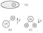
Drawn by us to help you understand the concept clearly, and verified to make sure it's accurate. For exams, practice from your textbook's own diagram.
What this figure shows. Panel (a) shows a generic polar molecule schematically, with its centre of positive charge (protons, marked +) and centre of negative charge (electrons, marked -) drawn as two visibly SEPARATED points within the molecule's outline, connected by a small arrow representing its permanent dipole moment. Panel (b) shows the specific structure of the HCl molecule, with the chlorine atom's larger negative charge centre and the hydrogen atom's positive charge centre offset from each other along the H-Cl bond. Panel (c) shows the bent structure of the water molecule , its two O-H bonds drawn meeting at the characteristic angle of about , with the oxygen atom's negative centre and the combined hydrogen positive centre clearly offset -- the geometric reason water has an unusu …
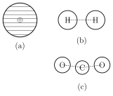
Drawn by us to help you understand the concept clearly, and verified to make sure it's accurate. For exams, practice from your textbook's own diagram.
What this figure shows. Panel (a) shows a generic non-polar molecule schematically, with its centre of positive charge and centre of negative charge drawn COINCIDING at the exact same central point (zero separation, zero dipole moment). Panel (b) shows the symmetric structure of the molecule (two identical hydrogen atoms, charge centres coinciding at the molecule's midpoint by symmetry). Panel (c) shows the linear, symmetric structure of (carbon centred between two oxygen atoms arranged in a straight line), whose overall symmetry likewise places its positive and negative charge centres at the very same point, giving it zero net dipole moment despite each in …
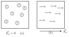
Drawn by us to help you understand the concept clearly, and verified to make sure it's accurate. For exams, practice from your textbook's own diagram.
What this figure shows. Panel (a) shows a block of non-polar dielectric material in the ABSENCE of any external field, drawn filled with small, symmetric, undistorted molecule symbols (each with coincident positive/negative centres, zero net dipole), showing no net polarisation anywhere in the bulk material. Panel (b) shows the same block placed in a uniform external field (drawn as parallel field-line arrows passing through it): each molecule is now shown slightly distorted into a tiny induced dipole, all aligned in the SAME direction as the field, with a resulting thin layer of net positive induced charge appearing on the face the field points toward and a corresponding layer of negative induced charge on the opposite face -- the surface-charge pic …
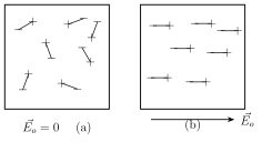
Drawn by us to help you understand the concept clearly, and verified to make sure it's accurate. For exams, practice from your textbook's own diagram.
What this figure shows. Panel (a) shows a block of polar dielectric material in the ABSENCE of any external field, drawn filled with small permanent dipole symbols (arrow pairs, each already separated since these are polar molecules) pointing in RANDOM, disordered directions throughout the material due to thermal agitation, so the dipoles cancel out to a net zero dipole moment overall despite each individual molecule already possessing one. Panel (b) shows the same block placed in a uniform external field : the individual permanent dipoles are now shown mostly ALIGNED with the field direction (though not perfectly, since thermal agitation still partially opposes full alignment), producing a net alignment/polarisation of t …
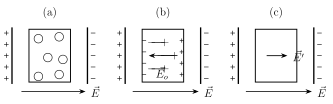
Drawn by us to help you understand the concept clearly, and verified to make sure it's accurate. For exams, practice from your textbook's own diagram.
What this figure shows. Panel (a) shows a rectangular dielectric slab placed between the two flat, oppositely-charged plates of a parallel-plate capacitor, filling (or partially filling) the gap between them, with the applied field from the plates' own charge drawn passing through the slab. Panel (b) shows the resulting induced surface charges on the dielectric slab's own two faces -- a layer of induced negative charge on the face nearer the capacitor's positive plate, and induced positive charge on the face nearer the negative plate -- together with the polarisation field these induced charges themselves produce, drawn as an arrow pointing OPPOSITE to the applied field , i.e. opposing it. Panel (c) shows the final NET field inside the dielectric as the vector sum (difference in magnitude, since they are antiparallel) of the applied field and the opposing polarisation field , drawn visibly SHORTER than the original applied-field arrow -- the reduced net field, $E'=E- …
Material | Min | Max -- Air | 1 | 1 -- Ebonite | 2.7 | 2.7 -- Glass | 3.8 | 14.5 -- Mica | 4 | 9 -- Paper | 1.5 | 3 -- Paraffin | 2 | 3 -- Porcelain | 5 | 6.5 -- Quartz | 5 | 5 -- Rubber | 2 | 4 -- Wood (dry) | 1.4 | 2.9 -- Metals | infinity | infinity. This is Table 8.1 of the printed textbook (page 203), listing the range of dielectric constant found across common materials, from air (essentially , indistinguishable from vacuum) up through glass and mica (some of the highest ordinary insulator values, up to about 9-14.5) to metals, whose dielectric constant is treated as effect …
Worked out. Notes that a dielectric's INDUCED dipole moment exists only while the external field is present and vanishes the instant the field is removed -- unlike a polar molecule's permanent dipole, which persists regardless. This vanishing-induced-dipole behaviour is exactly what explains a familiar everyday demonstration: a plastic comb charged by rubbing on dry hair attracts small, electrically NEUTRAL bits of paper, even though the paper carries no net charge of its own -- the comb's own field induces a temporary dipole in each paper bit, and the resulting non-uniform-field attraction (the induced dipole's near end is closer to, and therefore more strongly attracted to, the comb than its far end is repelled) pulls the paper toward the comb; the attraction disappears the moment the comb is taken away, …