Physics · Ch 8 — Electrostatics
Capacitors and Capacitance, Combination of Capacitors in Series and Parallel
Capacitors and Capacitance, Combination of Capacitors in Series and Parallel
Class XI covered the RESISTOR: a component that allows current to pass through it, but which only ever DISSIPATES the associated electrical energy as heat, with no capacity to store it. A genuinely different kind of device is needed for a circuit to STORE electrical energy for later use -- and the most common such arrangement is a pair of conducting plates carrying equal and opposite charges, separated by some dielectric medium (which may simply be air, or vacuum).
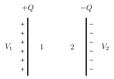
For two conductors 1 and 2, carrying charges and respectively, with potential difference between them, the field in the region between them -- and hence the potential difference itself -- is always directly proportional to the magnitude of the charge placed on them. Since , the ratio is therefore a CONSTANT for any given pair of conductors, called the CAPACITANCE, : a purely geometric property, depending only on the size, shape, separation and any intervening dielectric of the two-conductor system -- never on or individually, which can each be varied freely while their ratio stays fixed.
The SI unit of capacitance is the FARAD (F), where : a capacitor is said to have a capacitance of exactly one farad if its potential difference rises by exactly 1 volt for every 1 coulomb of charge given to it. In practice, the farad turns out to be an enormous, almost never directly usable unit, so real capacitance values are almost always quoted in its much smaller sub-multiples: F, F, and F.
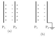
The underlying PRINCIPLE of how any capacitor manages to store more charge at a given voltage than an isolated conductor could is worth working through explicitly. Take an isolated, charged metal plate (area A, charge , potential V, so its own bare capacitance is ). Now bring a second, initially uncharged, INSULATED metal plate near it (not touching). By electrostatic INDUCTION, a negative charge is induced on 's face nearer , and an equal positive charge appears on 's farther face. Because the induced negative charge on the near face is CLOSER to , it has a stronger, more effective influence than the farther, weaker positive charge -- so on balance, 's own potential is LOWERED by 's mere presence. If 's outer (far) face is now connected to EARTH, its induced positive charge -- being genuinely free and mobile -- simply drains away into the ground, leaving only the induced negative charge bound on 's near face (held in place purely by its attraction to 's own positive charge); this earthing step lowers 's net potential difference still further. Since capacitance is charge divided by potential difference, and the charge on has not changed at all while its effective potential difference has been driven down, the two-plate arrangement's capacitance must be GREATER than 's own isolated : bringing an earthed conductor near a charged one always raises the overall system's capacitance. This is the general PRINCIPLE common to every capacitor, whatever its specific geometry. …
Drawn by us to help you understand the concept clearly, and verified to make sure it's accurate. For exams, practice from your textbook's own diagram.
What this figure shows. Two arbitrarily-shaped conductors, labelled 1 and 2, placed near each other, with conductor 1 carrying charge and conductor 2 carrying an equal and opposite charge ; the potential difference between them is marked as , and a set of field lines is drawn running from conductor 1 to conductor 2 in the space between them -- the general definition figure for ANY pair of oppositely-charged conductors forming a capacitor, regardless of their specific shape, …
Drawn by us to help you understand the concept clearly, and verified to make sure it's accurate. For exams, practice from your textbook's own diagram.
What this figure shows. Panel (a) shows an isolated charged metal plate (area A, charge ) with a second, uncharged insulated metal plate brought near it (not touching); induction is shown producing a layer of negative charge on 's face nearer and an equal layer of positive charge on 's farther face. Panel (b) shows the same two-plate arrangement with 's OUTER (farther) face now connected by a wire to earth, draining away its induced positive charge, leaving only the induced negative charge bound on 's near face -- the sequence of panels together illustrating exactly how earthing the second plate lowers 's net potential difference an …
Worked out. electrons are transferred between two conductors, producing a potential difference V. Charge transferred C. Capacitance F -- a direct application of once the transferred charge is found from the elementary charge and the number of electrons moved. …
Worked out. Given , , , in a network, with in PARALLEL: . This combination is in SERIES with : . This result is in PARALLEL with the series combination of (): total so far . This is finally in SERIES with the unknown , and the whole network's equivalent capacitance is given as : solving gives -- a worked illustration of reducing a mixed network step by step, combining parallel groups first and series groups aft …